Array substrate and manufacturing method thereof

A technology of array substrates and array substrate rows, applied in semiconductor/solid-state device manufacturing, electrical components, electric solid-state devices, etc., can solve problems such as wide frame, high production cost, and complicated production process

Inactive Publication Date: 2020-04-28
WUHAN CHINA STAR OPTOELECTRONICS SEMICON DISPLAY TECH CO LTD
View PDF11 Cites 2 Cited by
  • Summary
  • Abstract
  • Description
  • Claims
  • Application Information

AI Technical Summary

Problems solved by technology

Among them, in the process of preparing CMOS circuits using the LTPS process, it is necessary to use at least 9 photoresist masks and at least 4 doping processes (p-type ion doping, n-type ion doping, LDD doping, etc.) Miscellaneous and Ch doping), the production process is complicated, the production cost is high, and the frame is wide

Method used


Image

  • Array substrate and manufacturing method thereof
  • Array substrate and manufacturing method thereof
  • Array substrate and manufacturing method thereof

Examples


Embodiment Construction

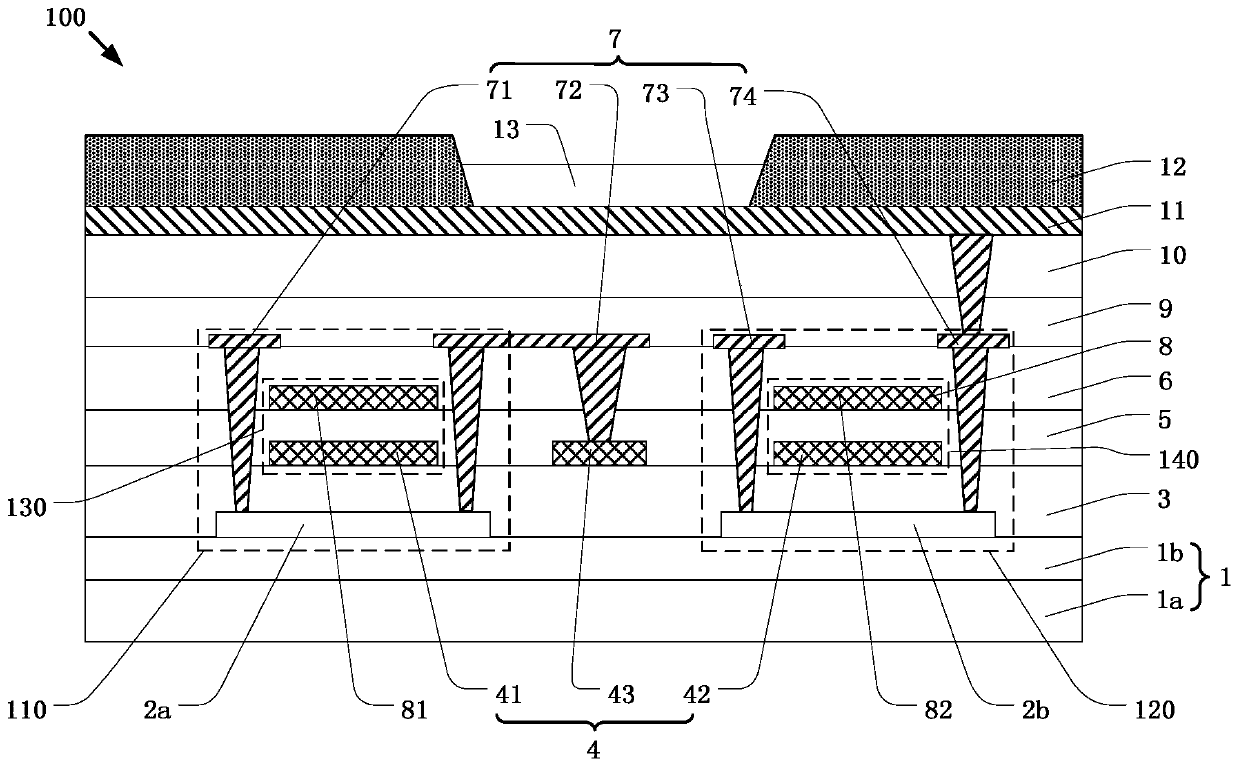
[0050] The following descriptions of the various embodiments refer to the accompanying drawings to illustrate specific embodiments in which the invention may be practiced. The directional terms mentioned in the present invention, such as [top], [bottom], [front], [back], [left], [right], [inside], [outside], [side], etc., are only for reference The orientation of the attached schema. Therefore, the directional terms used are used to illustrate and understand the present invention, but not to limit the present invention. In the figures, structurally similar elements are denoted by the same reference numerals.

[0051] The accompanying drawings of the present invention are only used to illustrate the relative positional relationship and electrical connection relationship. The layer thickness of some parts is drawn in an exaggerated way for easy understanding. The layer thickness in the drawings does not represent the proportional relationship of the actual layer thickness.

[...


PUM


Abstract

The invention provides an array substrate and a manufacturing method thereof. The array substrate is provided with a display area and an array substrate row driving area. The array substrate comprisesan underlayer substrate, a low-temperature polycrystalline silicon thin film transistor unit, a metal oxide transistor unit, a first capacitor and a second capacitor, wherein the low-temperature polycrystalline silicon thin film transistor unit is located on the underlayer substrate and located in the display area and the array substrate row driving area; the first capacitor is arranged corresponding to the low-temperature polycrystalline silicon thin film transistor unit; the metal oxide transistor unit is located on the underlayer substrate and located in the array substrate row driving area, and the metal oxide transistor unit is arranged in a mode of being spaced from the low-temperature polycrystalline silicon thin film transistor unit; and the second capacitor is arranged corresponding to the metal oxide transistor unit. According to the invention, the circuit structure of the low-temperature polycrystalline silicon thin film transistor unit is adopted in the display area of thearray substrate, so that an ultra-narrow frame is realized, the process is simplified, and the production cost is low.

Description

technical field [0001] The present invention relates to the display field, in particular to an array substrate and a manufacturing method thereof. Background technique [0002] Organic light-emitting diode (OLED) display is an emerging flat-panel display, which has excellent characteristics such as self-illumination, high contrast, thin thickness, wide viewing angle, fast response speed, and can be used for flexible display panels. , so it has very good development prospects. [0003] Thin film transistors are classified into amorphous silicon thin film transistors (a-Si TFT), low temperature polysilicon (Low Temperature Poly-silicon, LTPS) thin film transistors, and metal oxide (metal oxide) thin film transistors. Among them, amorphous silicon thin film transistors and low-temperature polysilicon thin film transistors are silicon-based thin film transistors, which have the advantages of fast switching speed and large driving current, and can be used for OLED display pixel ...

Claims


Application Information

Patent Timeline
Patent Type & Authority Applications(China)
IPC IPC(8): H01L27/12H01L27/32H01L21/77
CPCH01L27/1255H01L27/1248H01L27/124H01L27/1288H10K59/122H10K59/1213
Inventor 王选芸
Owner WUHAN CHINA STAR OPTOELECTRONICS SEMICON DISPLAY TECH CO LTD
Why Eureka
Try Eureka