A method for time alignment of multi-sensor data and data acquisition equipment
A data acquisition device and time alignment technology, applied in transmission systems, multiplexing communications, digital transmission systems, etc., can solve problems such as synchronization data errors, failure to meet the positioning accuracy of automatic driving, etc., and achieve the effect of improving multi-transmission
- Summary
- Abstract
- Description
- Claims
- Application Information
AI Technical Summary
Problems solved by technology
Method used
Image

Examples
Embodiment 1
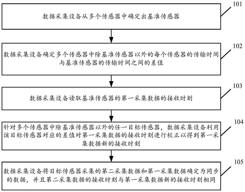
[0058] see figure 1 , figure 1 It is a schematic flowchart of a time alignment method for multi-sensor data disclosed in an embodiment of the present invention. Such as figure 1 As shown, the multi-sensor data method may include the following steps:
[0059] 101. The data collection device determines a reference sensor from multiple sensors.
[0060] In the embodiment of the present invention, the above-mentioned multiple sensors may include a camera, a satellite positioning device (such as a GPS device, a Beidou positioning device), an inertial navigation unit (Inertial measurement unit, IMU), a wheel speedometer, a radar, etc., the embodiment of the present invention No limit.
[0061] The transmission time required for the reference sensor to transmit data to the processor of the data acquisition device is greater than the transmission time required for any sensor other than the reference sensor to transmit data to the processor, that is, the reference sensor transmits ...
Embodiment 2
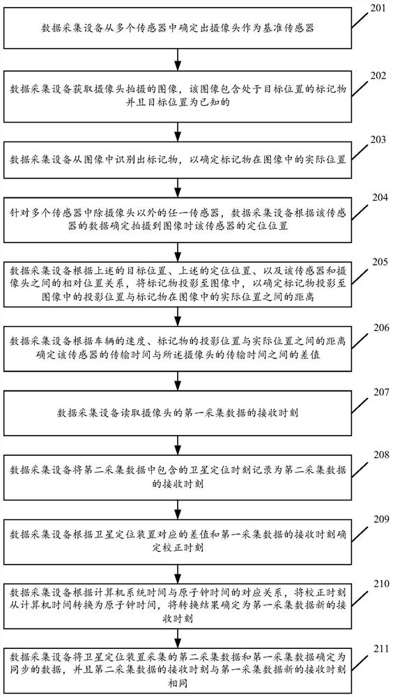
[0072] see figure 2 , figure 2 It is a schematic flowchart of a time alignment method for multi-sensor data disclosed in an embodiment of the present invention. Such as figure 2As shown, the multi-sensor data method may include the following steps:
[0073] 201. The data collection device determines a camera from multiple sensors as a reference sensor.
[0074] Among the multiple sensors mentioned above, the image data collected by the camera has a large amount of data and involves operations such as data encoding and decoding during transmission. The transmission time of image data is generally longer than that of other sensor data. Therefore, the camera can be determined as the reference sensor. With the camera as the reference sensor, visual information can be used as much as possible for data fusion, which can further improve the accuracy of data fusion. This is also one of the invention points of the present invention. In addition, by executing the following step...
Embodiment 3
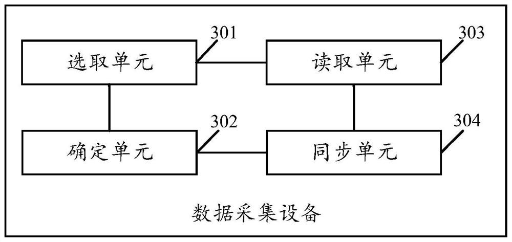
[0102] see image 3 , image 3 It is a schematic structural diagram of a data acquisition device disclosed in an embodiment of the present invention. Such as image 3 As shown, the data acquisition equipment may include:
[0103] The selection unit 301 is configured to determine a reference sensor from the plurality of sensors, and the transfer time required for the reference sensor to transmit data to the processor is greater than the time required for any sensor in the plurality of sensors except the reference sensor to transmit data to the processor. the required transmission time;
[0104] In the embodiment of the present invention, the above-mentioned multiple sensors may include a camera, a satellite positioning device, an inertial navigation unit, a wheel speedometer, a radar, etc., which are not limited in the embodiment of the present invention.
[0105] A determination unit 302, configured to determine the difference between the transmission time of each sensor i...
PUM
 Abstract
Description
Claims
Application Information
 - R&D
- Intellectual Property
- Life Sciences
- Materials
- Tech Scout
- Unparalleled Data Quality
- Higher Quality Content
- 60% Fewer Hallucinations
Browse by: Latest US Patents, China's latest patents, Technical Efficacy Thesaurus, Application Domain, Technology Topic, Popular Technical Reports.
© 2025 PatSnap. All rights reserved.Legal|Privacy policy|Modern Slavery Act Transparency Statement|Sitemap|About US| Contact US: help@patsnap.com