

Obstacle avoiding method and device of robot and robot
A robot and obstacle avoidance technology, applied in the field of robot navigation, can solve problems such as difficult and effective obstacle avoidance for robots, and achieve the effect of improving obstacle avoidance problems and improving obstacle avoidance efficiency
- Summary
- Abstract
- Description
- Claims
- Application Information
AI Technical Summary
Problems solved by technology
Method used
Image

Examples
Embodiment Construction
[0029] The following will clearly and completely describe the technical solutions in the embodiments of the present application with reference to the accompanying drawings in the embodiments of the present application. Obviously, the described embodiments are only part of the embodiments of the present application, not all of them. Based on the embodiments in this application, all other embodiments obtained by persons of ordinary skill in the art without making creative efforts belong to the scope of protection of this application.
[0030] The robot described in the robot embodiment of this application can be a smart home robot, such as a cleaning robot such as a sweeping robot or a vacuum robot, and of course can also be other commercial robots, civil robots, industrial robots, etc.
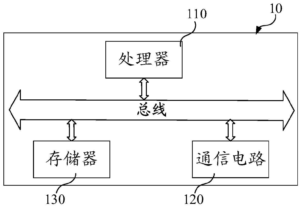
[0031] refer to figure 1 , taking a sweeping robot as an example, the robot 10 may include a processor 110 , a communication circuit 120 and a memory 130 . Processor 110 may communicate with c...
PUM
 Abstract
Description
Claims
Application Information