
Path planning method and industrial robot

An industrial robot and path planning technology, applied in manipulators, manufacturing tools, program-controlled manipulators, etc., can solve problems such as low efficiency, inability to automatically identify obstacles, and low accuracy, avoiding redundant calculations, and improving obstacle avoidance and path planning. The effect of efficiency

Active Publication Date: 2021-05-28
深圳辰视智能科技有限公司
View PDF6 Cites 1 Cited by
  • Summary
  • Abstract
  • Description
  • Claims
  • Application Information

AI Technical Summary

Problems solved by technology

[0003] However, this method requires multiple calculations and multiple plannings, and the efficiency is low. Moreover, this calculation method is often complicated, cannot automatically identify obstacles, and has low precision.

Method used


Image

  • Path planning method and industrial robot
  • Path planning method and industrial robot
  • Path planning method and industrial robot

Examples


Embodiment 1

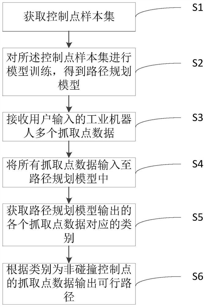
[0055] A path planning method, see figure 1 , including the following steps:

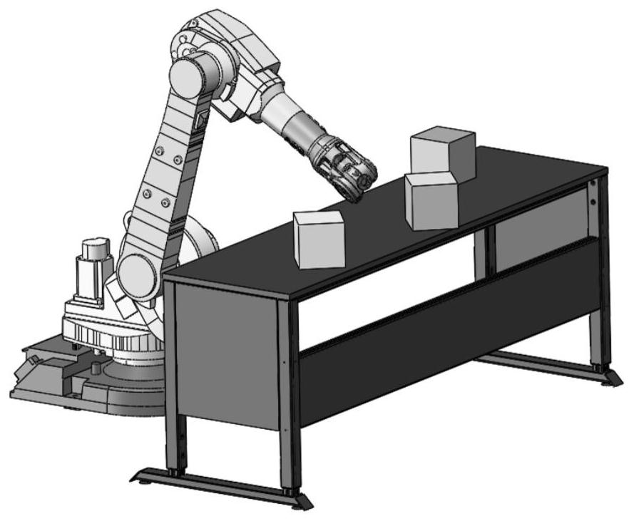
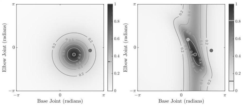
[0056] S1: Obtain a control point sample set; the samples in the control point sample set include historical grab point data and their categories of industrial robots; the categories are collision control points or non-collision control points, such as figure 2 shown;

[0057] Specifically, the historical grab point data is the position x of the end axis of the industrial robot n , where x n ∈R D , D is the dimension of the vector space R in the real number field, n takes a value from 1 to N, and N is the number of end axes of the industrial robot. The position x of the end axis of the industrial robot n Visual recognition technology can be used to obtain the pose of the flange at the end of the robot and the pose of the workpiece through image data and point cloud data.

[0058] The category is y n , where y n ∈{1,-1}; when y n = 1, the category is a non-collision control point, that is, ...

Embodiment 2

[0090] An industrial robot includes a processor and a memory, the processor and the memory are connected to each other, wherein the memory is used to store a computer program, the computer program includes program instructions, and the processor is configured to call the The program instruction executes the path planning method described in the first embodiment.

[0091] It should be understood that in the embodiment of the present invention, the so-called processor may be a central processing unit (Central Processing Unit, CPU), and the processor may also be other general-purpose processors, digital signal processors (Digital Signal Processor, DSP), dedicated integrated Circuit (Application Specific Integrated Circuit, ASIC), off-the-shelf programmable gate array (Field-Programmable Gate Array, FPGA) or other programmable logic devices, discrete gate or transistor logic devices, discrete hardware components, etc. A general-purpose processor may be a microprocessor, or the pro...


PUM


Abstract

The invention provides a path planning method and an industrial robot. The path planning method comprises the following steps of: acquiring a control point sample set; performing model training on the control point sample set to obtain a path planning model; receiving a plurality of grabbing point data of the industrial robot input by a user; inputting all the grabbing point data into the path planning model; acquiring the category corresponding to each grabbing point data output by the path planning model; and outputting a feasible path according to the grabbing point data of which the category is a non-collision control point. According to the path planning method, the historical conditions of a plurality of grabbing points of the industrial robot are acquired for model training, so that mechanical limiting and mistaken grabbing are avoided when the industrial robot grabs. In addition, an obstacle avoidance algorithm based on an SVM algorithm model is provided for model training, a mechanical arm path planning algorithm is accurately set, redundant calculation in the traditional path planning process is avoided, and the obstacle avoidance and path planning efficiency of the industrial robot is effectively improved.

Description

technical field [0001] The invention belongs to the technical field of intelligent control, and in particular relates to a path planning method and an industrial robot. Background technique [0002] At present, the path planning method of industrial robots first calculates the coordinates of obstacles relative to the industrial robot, then uses kinematics inverse solution to determine the angle of each axis of the industrial robot, and finally plans the rotation of the industrial robot axis through the method of function interpolation. [0003] However, this method requires multiple calculations and multiple plannings, and the efficiency is low. Moreover, this calculation method is often complicated, cannot automatically identify obstacles, and has low precision. Contents of the invention [0004] Aiming at the defects in the prior art, the present invention provides a path planning method and an industrial robot, which effectively improves the obstacle avoidance and path ...

Claims


Application Information

Patent Timeline
Patent Type & Authority Applications(China)
IPC IPC(8): B25J9/16
CPCB25J9/16B25J9/1664
Inventor 陈先开李攀张焱
Owner 深圳辰视智能科技有限公司
Learn More