
Coil Units and Winding Holders for Low Pole Count Rotors

A coil device and coil winding technology, applied in the direction of winding conductive materials, superconducting magnets/coils, transformers/reactors installation/support/suspension, etc., can solve problems such as high weight, high material consumption, and large space requirements

Active Publication Date: 2022-07-15
SIEMENS ENERGY GLOBAL GMBH CO & KG
View PDF13 Cites 0 Cited by
  • Summary
  • Abstract
  • Description
  • Claims
  • Application Information

AI Technical Summary

Problems solved by technology

Due to the winding head, a greater space requirement is created and the rotor produced with such a windi

Method used


Image

  • Coil Units and Winding Holders for Low Pole Count Rotors
  • Coil Units and Winding Holders for Low Pole Count Rotors
  • Coil Units and Winding Holders for Low Pole Count Rotors

Examples


Example Embodiment

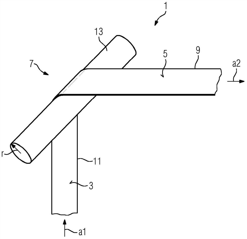
[0054] exist figure 1 A schematic representation of the strip conductor 1 in the inversion region 7 of the coil arrangement according to the invention is shown in FIG. Such an inversion region 7 can in principle occur in any region of the coil winding that is part of such a coil arrangement. It is important in connection with the present invention that the strip conductor 1 achieves a significant change of direction in such an inversion region 7 and at the same time changes the orientation of its two main surfaces. Therefore, the longitudinal direction of the strip conductor 1 is figure 1 In the left-hand region of the drawing, the strip conductors extend vertically in the direction a1 in the shown figure, while in the right-hand part of the drawing, the strip conductors are horizontally in the drawing in the direction a2 after passing the inversion region 7 . That is, the longitudinal direction of the strip conductor 1 is changed by about 90° here. On the left, the strip ...


PUM


Abstract

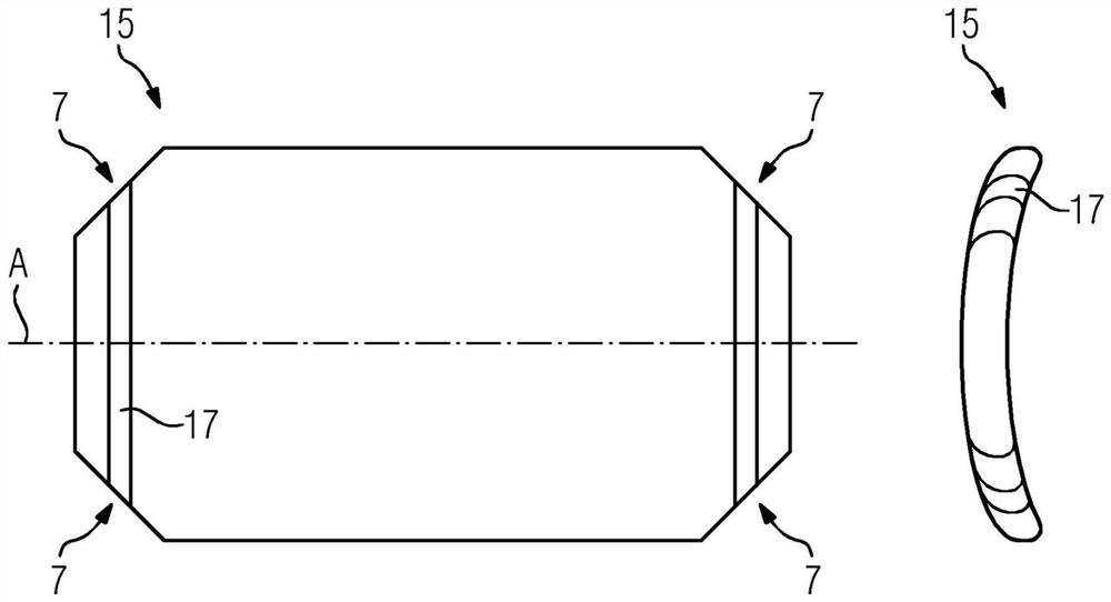
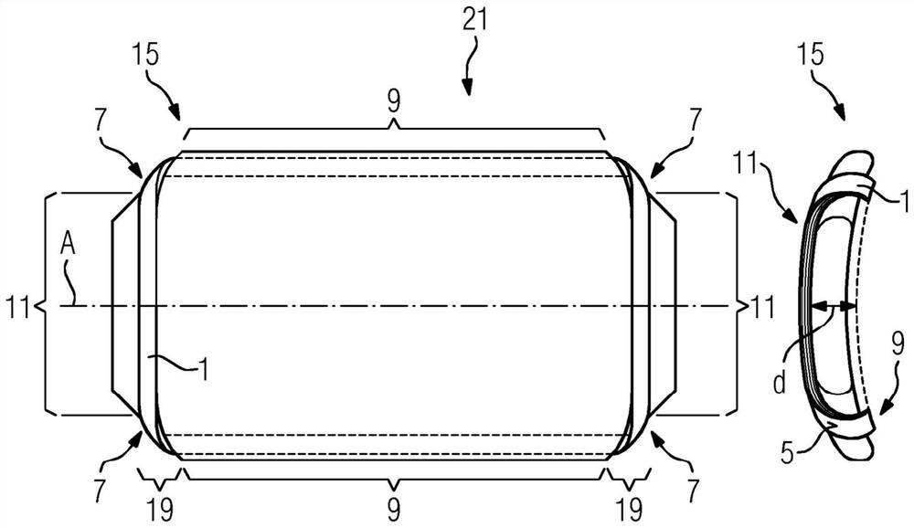
The invention relates to a superconducting coil arrangement (23) having at least one coil winding (21, 21a-21d) comprising at least one turn (w) of a superconducting strip conductor (1). ),-wherein the strip conductor (1) has a first main surface (3) and a second main surface (5),-wherein the coil winding (21, 21a-21d) has at least one inversion region (7), in The strip conductors ( 1 ) are folded in the inversion region such that the strip conductors in the inversion region ( 7 ) have a pronounced change of direction in their longitudinal direction ( a1 , a2 ) and at the same time the The orientation of the two main surfaces (3, 5) with respect to the central axis (A) of the coil arrangement (23) changes. In addition, a rotor ( 25 ) with such a coil arrangement ( 23 ) and a winding carrier ( 15 ) are provided for winding one of the coil windings ( 21 , 21 a - 21 d ) contained in the winding carrier, and for the A method for manufacturing the coil windings (21, 21a-21d) is presented.

Description

technical field [0001] The invention relates to a superconducting coil arrangement having at least one coil winding comprising at least one turn of a superconducting strip conductor, wherein the strip conductor has a first main surface and a second main surface surface. The invention also relates to a rotor for an electric machine with such a coil arrangement, as well as a winding support for such a coil winding and a method for its manufacture. Background technique [0002] Superconducting strip conductors, in particular strip conductors with a planar thin superconducting coating on a metallic base strip, exhibit promising properties for the production of coil windings. This may in particular refer to the rotor winding or the stator winding of the electric machine, but also to magnetic coils or other types of coil windings. It is generally advantageous when using such superconducting strip conductors that the current can flow almost without losses at temperatures below th...

Claims


Application Information

Patent Timeline
IPC IPC(8): H01F6/06
CPCH01F6/06Y02E40/60H01F27/06H01F41/048H02K3/02
Inventor T.阿恩特M.P.奥门
Owner SIEMENS ENERGY GLOBAL GMBH CO & KG
Learn More