
Sheet metal part spraying system

A sheet metal parts, No. 1 technology, applied in the field of sheet metal parts spraying system, can solve problems such as health hazards, uneven spraying thickness, paint flow, etc., and achieve the effect of prolonging the service life

Inactive Publication Date: 2020-05-08
郭翩翩
View PDF0 Cites 3 Cited by
  • Summary
  • Abstract
  • Description
  • Claims
  • Application Information

AI Technical Summary

Problems solved by technology

[0002] Sheet metal parts are relatively common hardware accessories. For example, electrical cabinets and cabinet doors are sheet metal parts. The spraying of sheet metal parts refers to the coating of corresponding paint on the surface of sheet metal parts to improve the use of sheet metal parts. Performance, after the sheet metal parts are polished, there is often a lot of powder or dust adhered to the surface. These powders and dust will produce a large number of dust spots on the sheet metal parts during the subsequent spraying operation, which will affect the spraying effect.
[0003] At present, sheet metal is uniformly sprayed by hand-held spray guns and sprayed by machines, but uniform spraying by hand-held spray guns is prone to uneven spray thickness, and paint flow will occur. At the same time, it will also cause unsatisfactory phenomenon due to less paint surface, which will affect the quality of sheet metal spraying. , and when manual hand-held spray guns work, it consumes manpower, and the contact with the paint is closer during manual spraying, which is likely to cause health hazards

Method used


Image

  • Sheet metal part spraying system
  • Sheet metal part spraying system
  • Sheet metal part spraying system

Examples


Embodiment Construction

[0026] In order to make the technical means, creative features, goals and effects achieved by the present invention easy to understand, the present invention will be further elaborated below in conjunction with the embodiments.

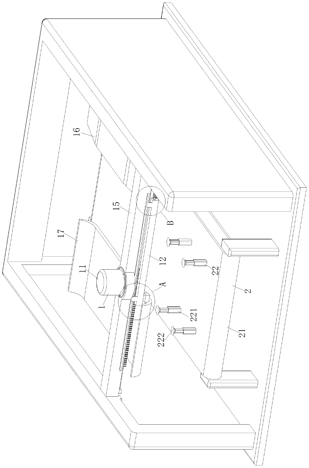
[0027] like Figure 1 to Figure 6 As shown, a kind of sheet metal spraying system of the present invention comprises a spraying cabin body, and an automatic control system is arranged in the spraying cabin body;

[0028] The automatic control system is used to control the spraying process of sheet metal parts, and the automatic control system includes a gas detection module, a time control module and an execution unit;

[0029] The gas detection module includes a gas detector, and the gas detector is used to detect the gas content inside the spraying cabin in real time, and transmit the detection result to the automatic control system;

[0030] The time control module includes a time timer, and the time timer is used to control the time when the shee...


PUM


Abstract

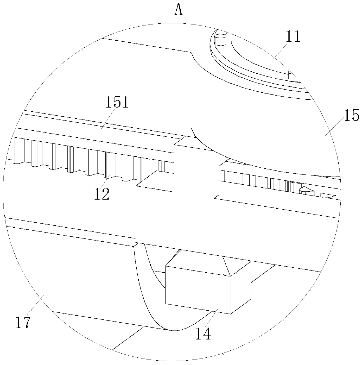
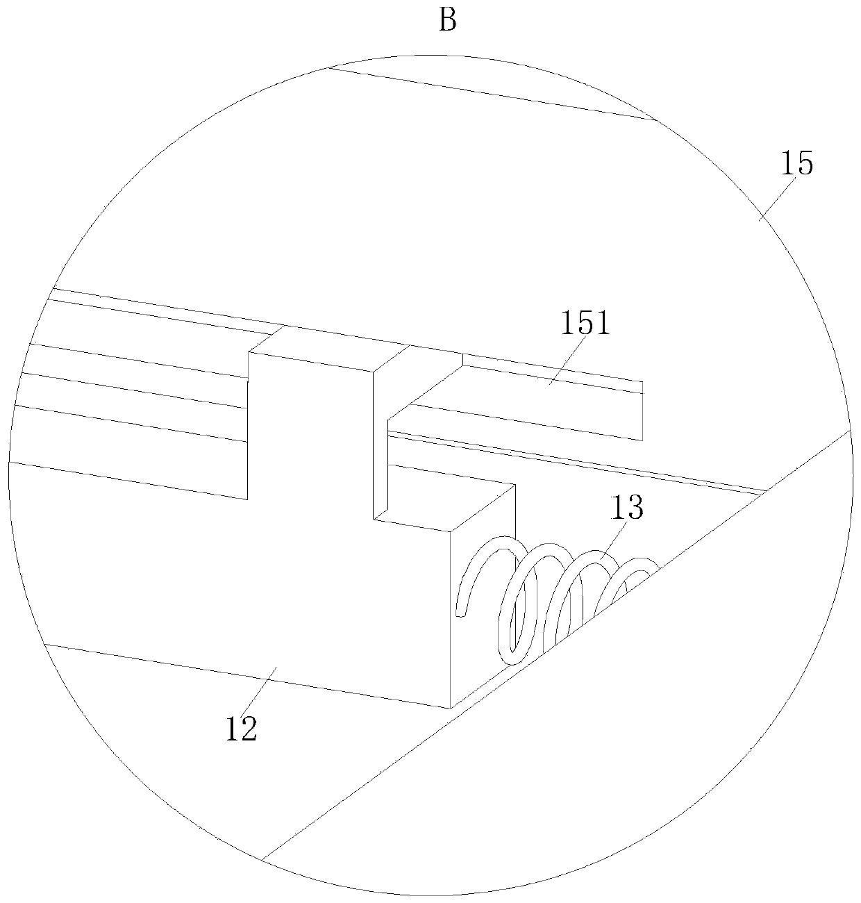
The invention belongs to the technical field of sheet metal part spraying, in particular to a sheet metal part spraying system. The sheet metal part spraying system comprises a spraying cabin body; anautomatic control system is arranged in the spraying cabin body; the automatic control system comprises a gas detecting module, a time control module and an executing unit; the executing unit comprises a spraying device and a conveying device; the spraying device comprises a first motor, a gear rack, a first spring and a spraying head; the conveying device comprises a conveying belt and supporting groups; the conveying belt is driven by a second motor; one end of the conveying belt is positioned on the front end surface of the spraying cabin body; the other end of the conveying belt is positioned on the rear end surface of the spraying cabin body; a plurality of the supporting groups are fixed to the conveying belt; four supporting rods are arranged in each supporting group; a sucking disc is arranged at an end part of each supporting rod; and the spraying of a sheet metal part is realized through the spraying device and the conveying device.

Description

technical field [0001] The invention belongs to the technical field of sheet metal spraying, in particular to a sheet metal spraying system. Background technique [0002] Sheet metal parts are relatively common hardware accessories. For example, electrical cabinets and cabinet doors are sheet metal parts. The spraying of sheet metal parts refers to the coating of corresponding paint on the surface of sheet metal parts to improve the use of sheet metal parts. Performance, after the sheet metal parts are polished, there is often a lot of powder or dust adhered to the surface. These powders and dust will produce a large number of dust spots on the sheet metal parts in the subsequent spraying operation, which will affect the spraying effect. [0003] At present, sheet metal is uniformly sprayed by hand-held spray guns and sprayed by machines, but uniform spraying by hand-held spray guns is prone to uneven spray thickness, and paint flow will occur. At the same time, it will also...

Claims


Application Information

Patent Timeline
IPC IPC(8): B05B13/04B05B14/00B05B15/50B05B13/02B05B12/02
CPCB05B12/02B05B13/0221B05B13/041B05B14/00B05B15/50
Inventor 郭翩翩程郎陆玉琴
Owner 郭翩翩
Learn More