Inertial equipment mounting base deformation measuring device and method

A technology for installing bases and inertial equipment, which is used in measuring devices, measuring instruments, surveying and navigation, etc.

Inactive Publication Date: 2020-05-08
TIANJIN NAVIGATION INSTR RES INST
View PDF17 Cites 0 Cited by
  • Summary
  • Abstract
  • Description
  • Claims
  • Application Information

AI Technical Summary

Problems solved by technology

However, the measurement accuracy of the electronic level instrument under dynamic conditions is affected by the ship's inclination angle, swing amplitude and swing period.

Method used


Image

  • Inertial equipment mounting base deformation measuring device and method
  • Inertial equipment mounting base deformation measuring device and method
  • Inertial equipment mounting base deformation measuring device and method

Examples


Embodiment Construction

[0019] The present invention will be described in further detail below in conjunction with the drawings and specific examples. The following examples are only descriptive, not restrictive, and cannot limit the protection scope of the present invention.

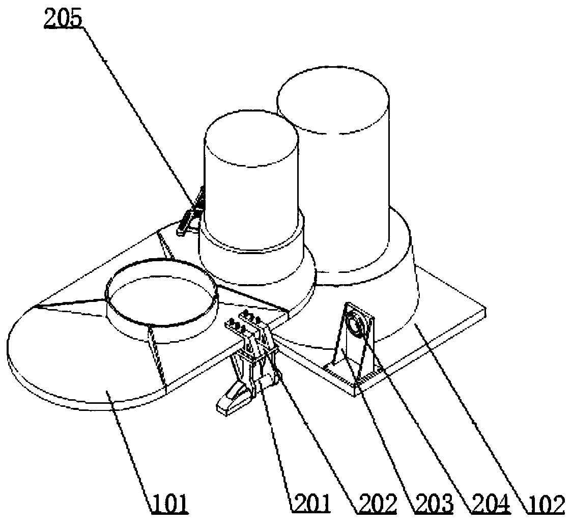
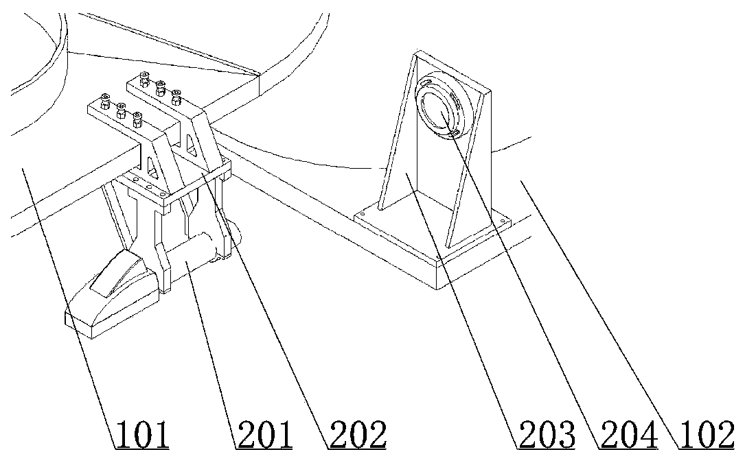
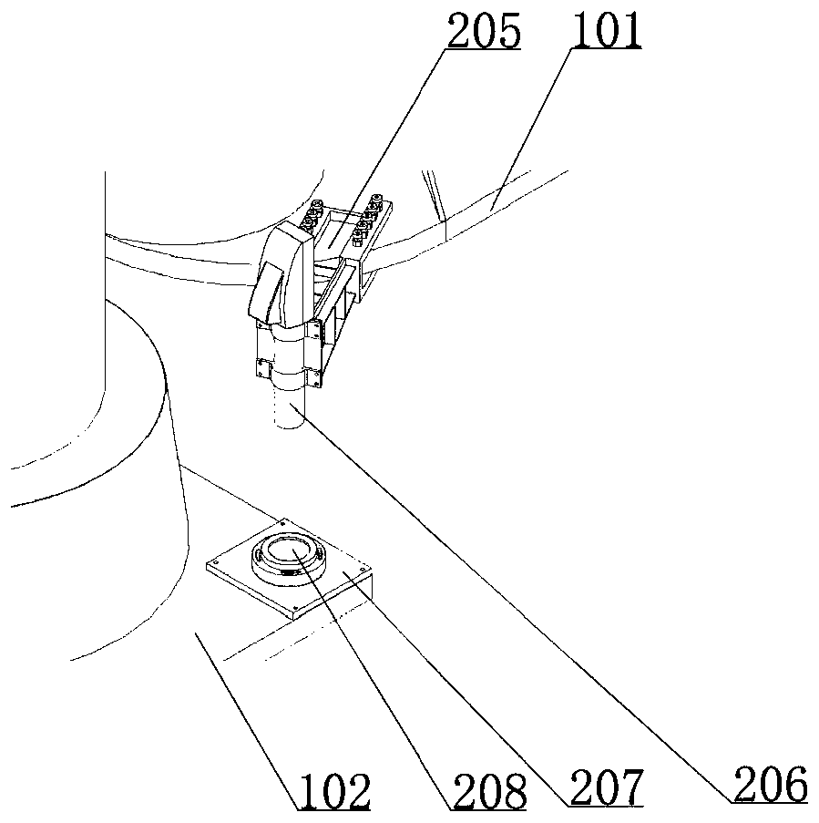
[0020] A kind of inertial equipment installation base deformation measurement device, please refer to Figure 1-3 , including an autocollimator hanger 205 for horizontal attitude observation, an autocollimator hanger 202 for azimuth attitude observation, an autocollimator 206 for horizontal attitude observation, an autocollimator 201 for azimuth attitude observation, and a horizontal attitude mirror 208 , the azimuth attitude reflector 204 , the horizontal attitude reflector mount 207 and the azimuth attitude reflector mount 203 .

[0021] The autocollimator hanger for the observation of the horizontal attitude and the autocollimator hanger for the observation of the azimuth attitude are all installed on the main installation ...


PUM


Abstract

The invention relates to an inertial equipment mounting base deformation measuring device and method. The method is characterized by comprising the following steps; an autocollimator hanging bracket for horizontal attitude observation and an autocollimator hanging bracket for azimuth attitude observation being both mounted on a main mounting base of ship inertial equipment, and respectively mounting the autocollimator for horizontal attitude observation and the autocollimator for azimuth attitude observation on the autocollimator hanging bracket for horizontal attitude observation and the autocollimator hanging bracket for azimuth attitude observation; wherein the horizontal attitude reflector mounting seat and the azimuth attitude reflector mounting seat are both mounted on a ship inertial equipment auxiliary mounting base, and respectively mounting the horizontal attitude reflector and the azimuth attitude reflector on the horizontal attitude reflector mounting seat and the azimuth attitude reflector mounting seat; aligning the autocollimator for horizontal attitude observation with the horizontal attitude reflector, and aligning the azimuth attitude observation autocollimator with the azimuth attitude reflector. According to the invention, deformation measurement between the main mounting base and the auxiliary mounting base of the ship inertial equipment can be carried outdynamically.

Description

technical field [0001] The invention belongs to the technical field of inertial equipment detection, and specifically designs an inertial equipment installation base deformation measurement device and method. Background technique [0002] The conventional method for measuring the deformation of the installation base of inertial equipment is to use an electronic level. First, place the A probe of the electronic level on the main installation base of the inertial equipment of the ship, and then place the B probe of the electronic level on the inertial equipment of the ship. On the auxiliary installation base, the attitude change in a horizontal direction of the installation base of the inertial equipment of different ships is obtained by using the difference method. However, the measurement accuracy of the electronic level instrument under dynamic conditions is affected by the ship's inclination angle, swing amplitude and swing period. Contents of the invention [0003] The...

Claims


Application Information

Patent Timeline
IPC IPC(8): G01C15/00G01B21/32
CPCG01C15/00G01B21/32
Inventor 陈志刚王琳王凯徐凯宋高玲
Owner TIANJIN NAVIGATION INSTR RES INST
Why Eureka
Try Eureka