
Robot rotational joint driving device and method

A technology for rotating joints and driving devices, which is applied to fluid pressure actuating devices, mechanical equipment, servo motors, etc., can solve the problems of small inertia, high cost, complex structure of DC motors, etc., and achieves high output power, high reliability, and high reliability. Guaranteed accuracy

Active Publication Date: 2014-06-18
昆山市工业技术研究院有限责任公司
View PDF6 Cites 26 Cited by
  • Summary
  • Abstract
  • Description
  • Claims
  • Application Information

AI Technical Summary

Problems solved by technology

Although the DC servo motor has the advantages of fast response, large starting torque, small inertia, and smooth rotation, the structure of the DC servo motor is complex and the cost is high.
Some special-purpose rotating robots require a large output power of the drive device and a compact structure, that is, actuators with high power density to deal with the mass distribution of the robot. The current robot joint drive technology cannot solve this problem well.

Method used


Image

  • Robot rotational joint driving device and method
  • Robot rotational joint driving device and method

Examples


Embodiment Construction

[0035] At present, the joint drive of the rotary robot is mainly realized by the mechanical transmission actuator with the DC servo motor as the driving source, but the structure of the DC motor is complex and the cost is high. Some special-purpose rotating robots require high output power and compact structure of the drive device, that is, actuators with high power density to deal with the mass distribution of the robot. The current robot joint drive technology cannot solve this problem well.

[0036] Aiming at the deficiencies in the prior art, the present invention provides a robot rotary joint driving device and a driving method. The driving device uses a servo motor to drive a hydraulic actuator for output, and the output power is large, which can effectively solve the problem of high power, high power, and The compact structure of the rotary joint is required, and the driving device has a simple structure, is easy to implement, and has high reliability.

[0037] The tech...


PUM


Abstract

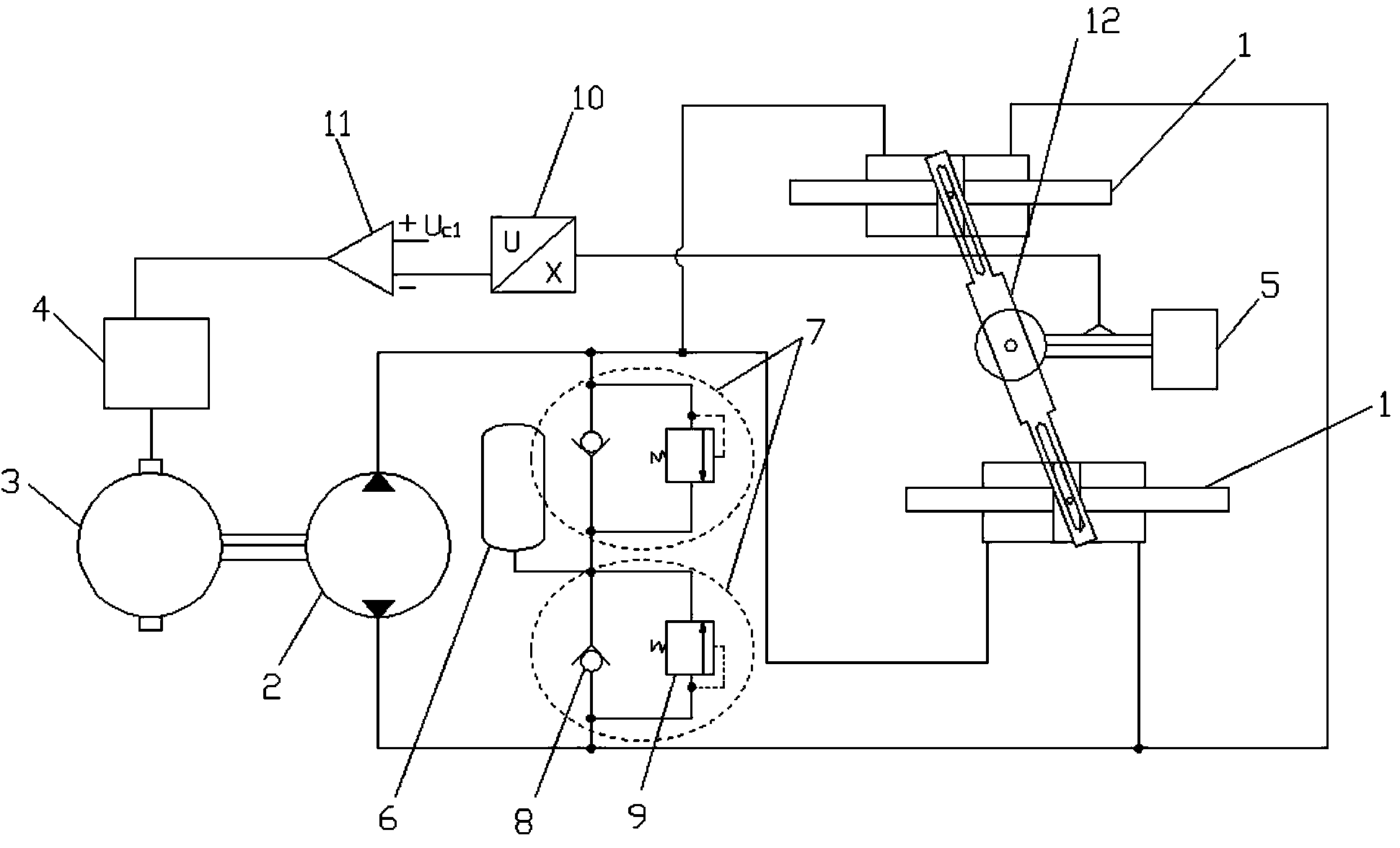
The invention discloses a robot rotational joint driving device which comprises a driving mechanism and an execution output mechanism. The driving mechanism comprises a servo motor and a hydraulic pump, the execution output mechanism comprises two hydraulic cylinders arranged in parallel, and a swinging rod is connected between pistons of the two hydraulic cylinders and can swing around the gyration center of the swinging rod under driving of the pistons at the two ends; a robot component is connected to the gyration center of the swinging rod and rotates along with swinging of the swinging rod; the driving device further comprises a detection module, a processing module and a motor controller. The execution output mechanism is driven by the servo motor to conduct outputting, the output power is high, and the requirement that a rotational operation robot needs high-power rotational joints of compact structures can be effectively met. Intermittent one-way turnover movement of a transmission shaft is achieved through one-way bearing transmission. A transmitter is used in cooperation with an amplifier, the rotation amount of the robot component is effectively adjusted, and the rotation accuracy and the rotation reliability are guaranteed. The robot rotational joint driving device is simple in structure and convenient to implement.

Description

technical field [0001] The invention belongs to the technical field of robot joint drive, and in particular relates to a robot rotary joint drive device and a drive method. Background technique [0002] At present, the vast majority of rotating robots use servo motors as the driving components of the joints. Most of the high-performance servo motors sold on the market have the characteristics of high speed and low torque, so they must be properly decelerated before they can be used to drive the various joints of the robot. In order to convert the motion of the driver into the motion of the robot, in addition to direct drive, it is necessary to change the speed of motion, etc., and it is also necessary to transmit the motion of the driver to the transmission mechanism at different locations. The motion transmission of the robot is achieved by combining these motion transformation and transmission mechanisms. [0003] The joint drive of the rotary robot developed by industri...

Claims


Application Information

Patent Timeline
IPC IPC(8): F15B9/09F15B1/02
Inventor 王鲁单胡友程胜张建伟
Owner 昆山市工业技术研究院有限责任公司
Learn More