Optical fiber sensing natural gas pipeline leakage event identification method and device

A natural gas pipeline, optical fiber sensing technology, applied in pipeline systems, gas/liquid distribution and storage, mechanical equipment, etc., can solve the problems of poor location accuracy of leakage events, many false alarms in the system, and narrow signal channels, to increase the effective The amount of characteristic information, the increase of the spectrum width, the effect of improving the induction sensitivity

Active Publication Date: 2013-03-27
BC P INC CHINA NAT PETROLEUM CORP +1
View PDF10 Cites 22 Cited by
  • Summary
  • Abstract
  • Description
  • Claims
  • Application Information

AI Technical Summary

Problems solved by technology

However, this type of technology is affected by interference events around the pipeline when monitoring leakage, has a high system false alarm rate, and has poor anti-interference ability
[0011] The traditional acoustic sensor-based leak detection method uses a pressure sensor that needs to be powered as the sound signal pickup device. Usually, two sensors are installed at both ends of the pipeline entering and leaving the station or valve chamber, and only one time difference can be obtained in the leakage signal acquisition. The positioning accuracy of leakage events is poor, and due to the narrow signal channel obtained, it is difficult to distinguish leakage from random vibration interference, and the system has many false alarms

Method used


Image

  • Optical fiber sensing natural gas pipeline leakage event identification method and device
  • Optical fiber sensing natural gas pipeline leakage event identification method and device
  • Optical fiber sensing natural gas pipeline leakage event identification method and device

Examples


Embodiment Construction

[0035] The present invention will be further described in conjunction with the accompanying drawings and embodiments, but the protection scope of the present invention should not be limited thereby.

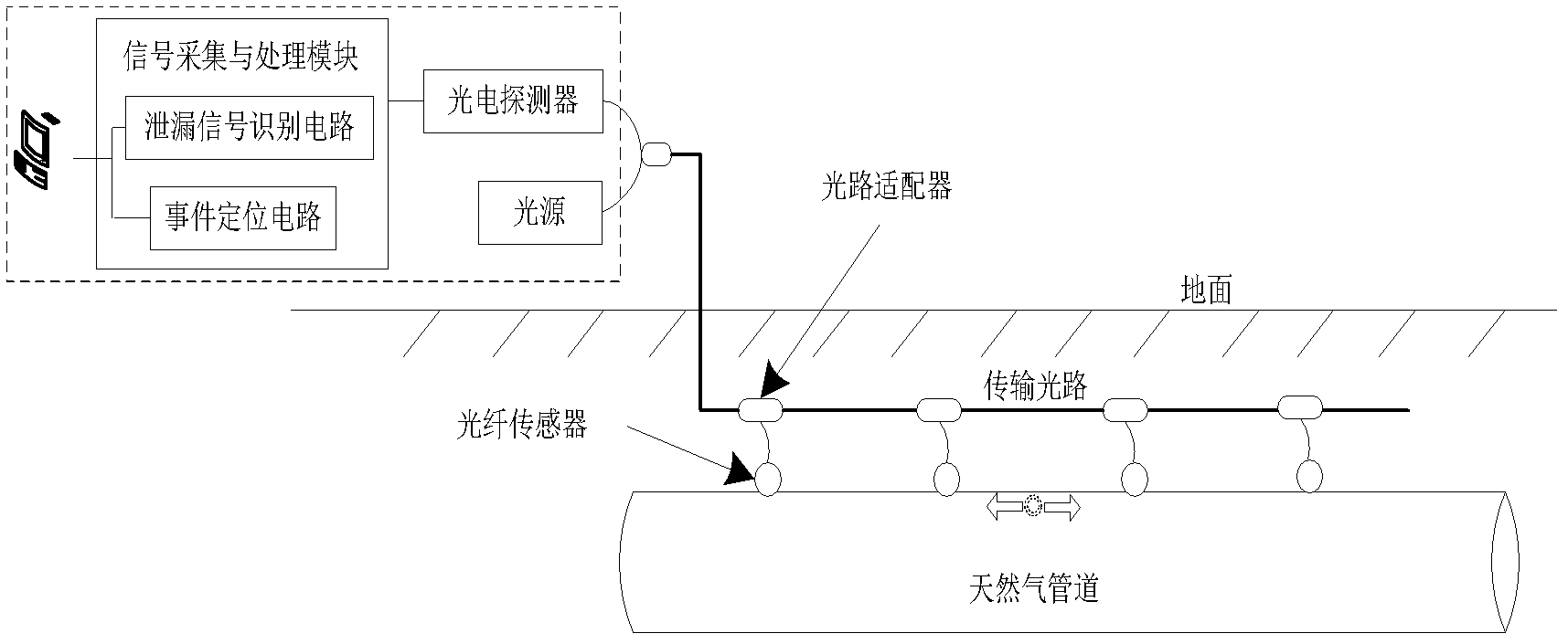
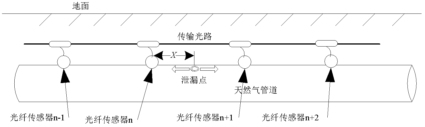
[0036] Embodiment. The composition of this example is as figure 1 As shown, a fiber optic sensor is installed at a certain distance on the pipeline body, and multiple fiber optic sensors form a fiber optic sensor group. A light source and a photoelectric detector, the output of the photodetector is connected to the signal acquisition and processing module, and the output of the signal acquisition and processing module is connected to the microcomputer. After the processing of the signal acquisition and processing module, the demultiplexing of each sensor in the sensor group is realized based on the mixed sensor group signal in the frequency division multiplexing mode, and the original leakage vibration wave signal is obtained.

[0037] The light source is a narrow-linewidth fibe...


PUM


Abstract

The invention relates to an optical fiber sensing natural gas pipeline leakage event identification method and an optical fiber sensing natural gas pipeline leakage event identification device, which relates to the field of a mechanical vibration measurement technology, an impact measurement technology and a pipeline system technology. A time domain feature (Pt) of a pipeline normal operation and leakage status signal, a frequency-domain characterization (Pf) and a noise characteristic (Pn) of an existing pipeline transmission signal and the waveshape recognition are comprehensively analyzed, a leakage confidence coefficient function model is built as follows: R=a1Pt+a2Pf-a3Pn, the leakage of a picked up vibration wave signal is evaluated to judge whether leakage happens to the pipeline or not, and different arithmetical parameters a1, a2 and a3 are arranged to regulate the confidence coefficient module according to the characteristics of the existing pipeline; the time domain, the frequency domain and wave form estimation performed on the leakage signal is that the signal can be accurately identified to be the leakage event according to a time-varying enveloping character and abruptness of the leakage signal and a center frequency distribution character of the stable leakage event signal, based on the feature classification of a stimulated leakage event. The optical fiber sensing natural gas pipeline leakage identification method and the optical fiber sensing natural gas pipeline leakage identification device provided by the invention can monitor the signal abnormalities in time and give an alarm with high accuracy at the primary state of the leakage.

Description

technical field [0001] The invention relates to a method and device for identifying leakage events of natural gas pipelines with optical fiber sensing, and relates to the technical fields of mechanical vibration measurement, impact measurement and pipeline systems. Background technique [0002] At present, the total length of pipelines built in the world has reached 2.5 million kilometers, which has surpassed the total mileage of railways and has become the main mode of energy transportation in the world. Oil transportation in developed countries and oil-producing regions in the Middle East has all realized pipelines. my country's pipelines have also developed rapidly in recent years, with a total length of more than 70,000 kilometers. A large energy pipeline network has initially formed across the east, west, north and south, covering the whole country, and connecting overseas. Pipeline transportation has become the deployment of strategic energy such as oil and gas. The mai...

Claims


Application Information

Patent Timeline
Patent Type & Authority Applications(China)
IPC IPC(8): F17D5/02
Inventor 张金权王小军焦书浩王飞刘素杰赵敏琴李刚崔海龙于立成张浩
Owner BC P INC CHINA NAT PETROLEUM CORP
Why Eureka
Try Eureka