Supercharge Your Innovation With Domain-Expert AI Agents!

Chip pin reader

A technology of foot reader and chip, which is applied in the direction of electric solid-state devices, semiconductor devices, semiconductor/solid-state device components, etc., can solve the problems of spending a lot of time wiring and cumbersome process, and achieve short time-consuming, simple and fast process The effect of wiring

Active Publication Date: 2020-05-08
SHUNDE POLYTECHNIC
View PDF7 Cites 0 Cited by
  • Summary
  • Abstract
  • Description
  • Claims
  • Application Information

AI Technical Summary

Problems solved by technology

Since the distance between the pins of the chip is relatively small, technicians need to spend a lot of time on wiring during the wiring process, and the process is cumbersome

Method used


Image

  • Chip pin reader
  • Chip pin reader
  • Chip pin reader

Examples


Embodiment Construction

[0019] The specific embodiments of the present invention will be further described below in conjunction with the accompanying drawings. It should be noted here that the descriptions of these embodiments are used to help understand the present invention, but are not intended to limit the present invention. In addition, the technical features involved in the various embodiments of the present invention described below may be combined with each other as long as they do not constitute a conflict with each other.

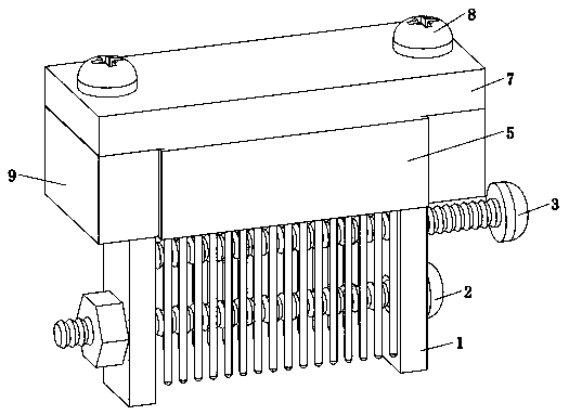
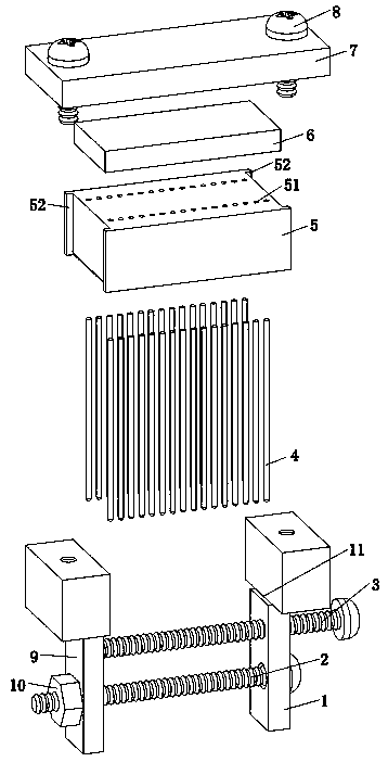
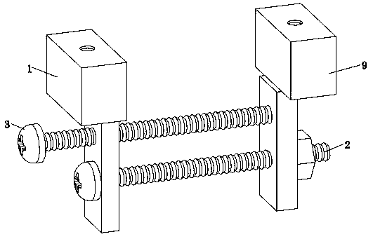
[0020] Such as Figure 1 to Figure 6 As shown, it is a chip reader, right splint 1, connecting bolt 2, left splint 9 and nut 10; said connecting bolt 2 passes through the right splint 1 and left splint 9 and is connected by a nut 10, and the nut 10 rotates Control the distance between the left splint 9 and the right splint 1; the upper part of the left side of the right splint 1 is provided with a right support platform 11, and the upper part of the right side of the le...


PUM


Abstract

The invention relates to a chip pin reader. The chip pin reader comprises a right clamping plate, connecting bolts, a left clamping plate, a nut, more than four probes, a mounting hole plate, a rubberpad, a cover plate and a connecting piece. The connecting bolts penetrate through the right clamping plate and the left clamping plate and are connected through the nut, and the nut rotates to control a distance between the left clamping plate and the right clamping plate. A left side and a right side of the mounting hole plate are supported on a right supporting table and a left supporting tablerespectively and located between the right clamping plate and the left clamping plate, the cover plate is located above the installation hole plate, the rubber pad is arranged below the cover plate,and a left end and a right end of the cover plate are arranged at an upper end of the left clamping plate and the upper end of the right clamping plate through the connecting piece. The chip pin reader has advantages that each pin of the chip can be quickly led out, wiring can be conveniently performed, consumed time is short, and a process is simple.

Description

technical field [0001] The invention relates to a chip reader. Background technique [0002] At present, in order to read the data of the chip on the circuit board, wires are directly connected to each pin of the chip, and then the data is read through an external device. Since the distance between the pins of the chip is relatively small, technicians need to spend a lot of time on wiring during the wiring process, and the process is cumbersome. Contents of the invention [0003] The object of the present invention is to overcome the disadvantages of the prior art and provide a chip pin reader, which can quickly lead out each pin of the chip, can be connected conveniently, takes a short time, and has a simple process. [0004] In order to achieve the above object, the present invention is achieved like this, it is a kind of chip pin reader, it is characterized in that comprising: [0005] Right splint, connecting bolt, left splint and nut; the connecting bolt passes thro...

Claims


Application Information

Patent Timeline
Patent Type & Authority Applications(China)
IPC IPC(8): H01L23/48H01L23/58H01R13/621
CPCH01L23/48H01L23/58H01R13/621
Inventor 李玉春余华明王斯焱林芝东潘桂芬
Owner SHUNDE POLYTECHNIC
Features
  • R&D
  • Intellectual Property
  • Life Sciences
  • Materials
  • Tech Scout
  • Unparalleled Data Quality
  • Higher Quality Content
  • 60% Fewer Hallucinations
Learn More