Inner rotor for drum-type permanent magnet speed regulator and drum-type permanent magnet speed regulator

A technology of permanent magnet governor and inner rotor, applied in permanent magnet clutches/brakes, magnetic circuit rotating parts, magnetic circuit shape/style/structure, etc., can solve problems such as insufficient heat dissipation efficiency

Pending Publication Date: 2020-05-08
CHONGQING PRD TECH
View PDF0 Cites 1 Cited by
  • Summary
  • Abstract
  • Description
  • Claims
  • Application Information

AI Technical Summary

Problems solved by technology

[0004] Based on this, the present invention overcomes the defects of the prior art and provides an inner rotor for a cylindrical pe

Method used


Image

  • Inner rotor for drum-type permanent magnet speed regulator and drum-type permanent magnet speed regulator
  • Inner rotor for drum-type permanent magnet speed regulator and drum-type permanent magnet speed regulator
  • Inner rotor for drum-type permanent magnet speed regulator and drum-type permanent magnet speed regulator

Examples


Embodiment approach 1

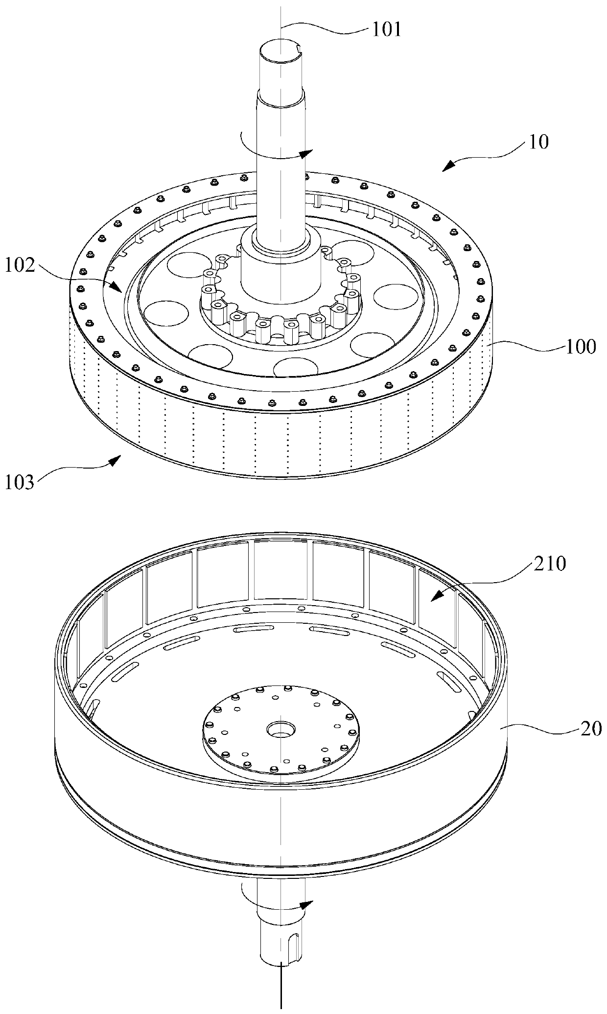
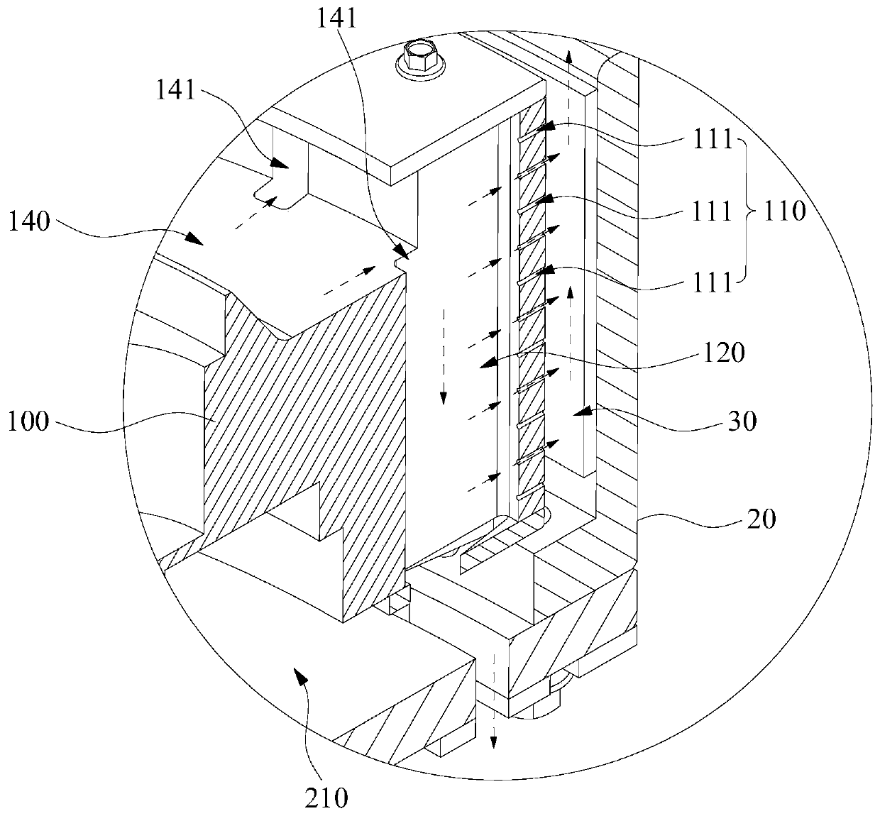
[0031] to combine image 3 , Figure 4 As shown, in one embodiment, an inner rotor 10 for a cylindrical permanent magnet governor includes an inner rotor body 100, and a centrifugal flow channel 110 is arranged inside the inner rotor body 100, and the outlet of the centrifugal flow channel 110 is located at on the radially outer peripheral surface of the inner rotor body 100 .

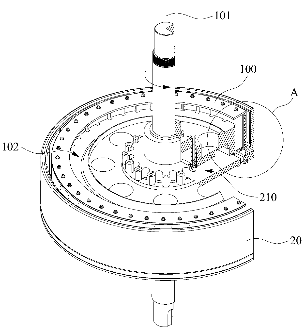
[0032] The inner rotor 10 for the above-mentioned cylindrical permanent magnet governor, combined with figure 1 , figure 2 and image 3As shown, when in use, the outer rotor 20 is used in conjunction with the inner rotor 10 for the cylindrical permanent magnet governor. The outer rotor 20 is provided with an accommodating cavity 210 , the inner rotor 10 is installed in the accommodating cavity 210 , and the radially outer peripheral surface of the inner rotor body 100 cooperates with the inner wall of the accommodating cavity 210 to form an air gap 30 . Since the outlet of the centrifugal channel...

Embodiment approach 2

[0052] to combine figure 1 , figure 2 and image 3 As shown, a cylindrical permanent magnet speed governor includes an outer rotor 20 and an inner rotor 10 for the cylindrical permanent magnet speed governor in any of the above-mentioned embodiments; the outer rotor 20 is provided with an accommodation cavity 210; the The inner rotor 10 is installed in the accommodating cavity 210 , and the radially outer peripheral surface of the inner rotor body 100 cooperates with the inner wall of the accommodating cavity 210 to form an air gap 30 .

[0053] The drum type permanent magnet governor includes an inner rotor 10 and an outer rotor 20 . The outer rotor 20 is provided with an accommodating cavity 210 , the inner rotor 10 is installed in the accommodating cavity 210 , and the radially outer peripheral surface of the inner rotor body 100 cooperates with the inner wall of the accommodating cavity 210 to form an air gap 30 . Since the outlet of the centrifugal channel 110 is loca...


PUM


Abstract

The invention relates to an inner rotor for a drum-type permanent magnet speed regulator and the drum-type permanent magnet speed regulator. The inner rotor for the drum-type permanent magnet speed regulator comprises an inner rotor body, a centrifugal flow channel is arranged in the inner rotor body, and the outlet of the centrifugal flow channel is located on the radial outer peripheral surfaceof the inner rotor body; when in use, the outer rotor is matched with the inner rotor for the cylindrical permanent magnet speed regulator. The outer rotor is provided with a containing cavity, the inner rotor is installed in the containing cavity, and the radial outer circumferential face of the inner rotor inner body is matched with the inner wall of the containing cavity in a spaced mode to form an air gap. The outlet of the centrifugal flow channel is positioned on the radial outer peripheral surface of the inner rotor body and is opposite to the inner wall of the containing cavity, so that the centrifugal flow channel can directly communicate with the air gap through the outlet of the centrifugal flow channel. Because the outlet of the centrifugal flow channel is located in the radialouter circumferential face of the inner rotor body, cooling liquid in the centrifugal flow channel can flow into the air gap through centrifugal force borne by the centrifugal flow channel, and the cooling liquid entering the air gap exchanges heat with the inner rotor and the outer rotor and then flows out of the air gap.

Description

technical field [0001] The invention relates to the technical field of permanent magnet speed regulation, in particular to an inner rotor for a barrel type permanent magnet speed governor and the barrel type permanent magnet speed governor. Background technique [0002] The barrel-type permanent magnet governor is a transmission device that transmits torque through the air gap. The existing barrel-type permanent magnet governor is mainly composed of two parts: an induction rotor and a permanent magnet rotor. The induction rotor is fixed on the drive shaft and connected to the motor end; the permanent magnet rotor is fixed on the load shaft and connected to the load. There is a gap between the induction rotor and the permanent magnet rotor. In this way, the connection between the motor and the load will be changed from the original mechanical connection to the magnetic connection. By adjusting the air gap distance or area between the permanent magnet rotor and the induction...

Claims


Application Information

Patent Timeline
IPC IPC(8): H02K49/10H02K1/32
CPCH02K1/32H02K49/10
Inventor 李明俊李金明林洁刘定文
Owner CHONGQING PRD TECH
Why Eureka
Try Eureka