Damping motor convenient to move

A technology of shock-absorbing springs and movable rods, applied in electrical components, electromechanical devices, electric components, etc., can solve the problems of inconvenient movement and large motor vibration, and achieve the effect of solving large vibration, reducing vibration and protecting the motor.

Inactive Publication Date: 2020-05-12
SUPERSOCO INTELLIGENT TECHNOLOGY (SHANGHAI) CO LTD
View PDF8 Cites 4 Cited by
  • Summary
  • Abstract
  • Description
  • Claims
  • Application Information

AI Technical Summary

Problems solved by technology

[0003] The existing motor vibrates greatly

Method used


Image

  • Damping motor convenient to move
  • Damping motor convenient to move
  • Damping motor convenient to move

Examples


Example Embodiment

[0020] Example 1

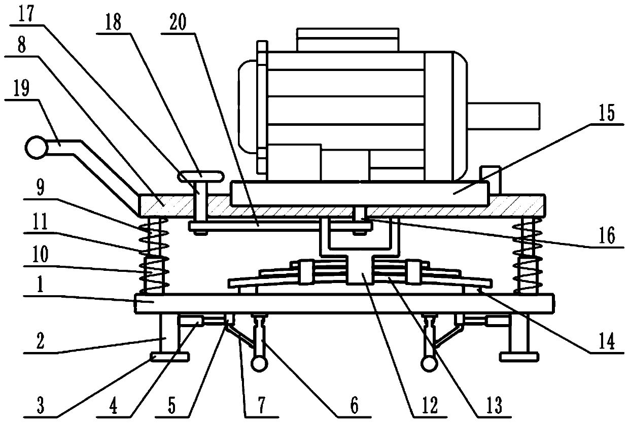
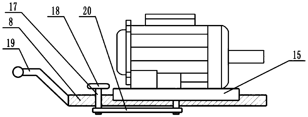
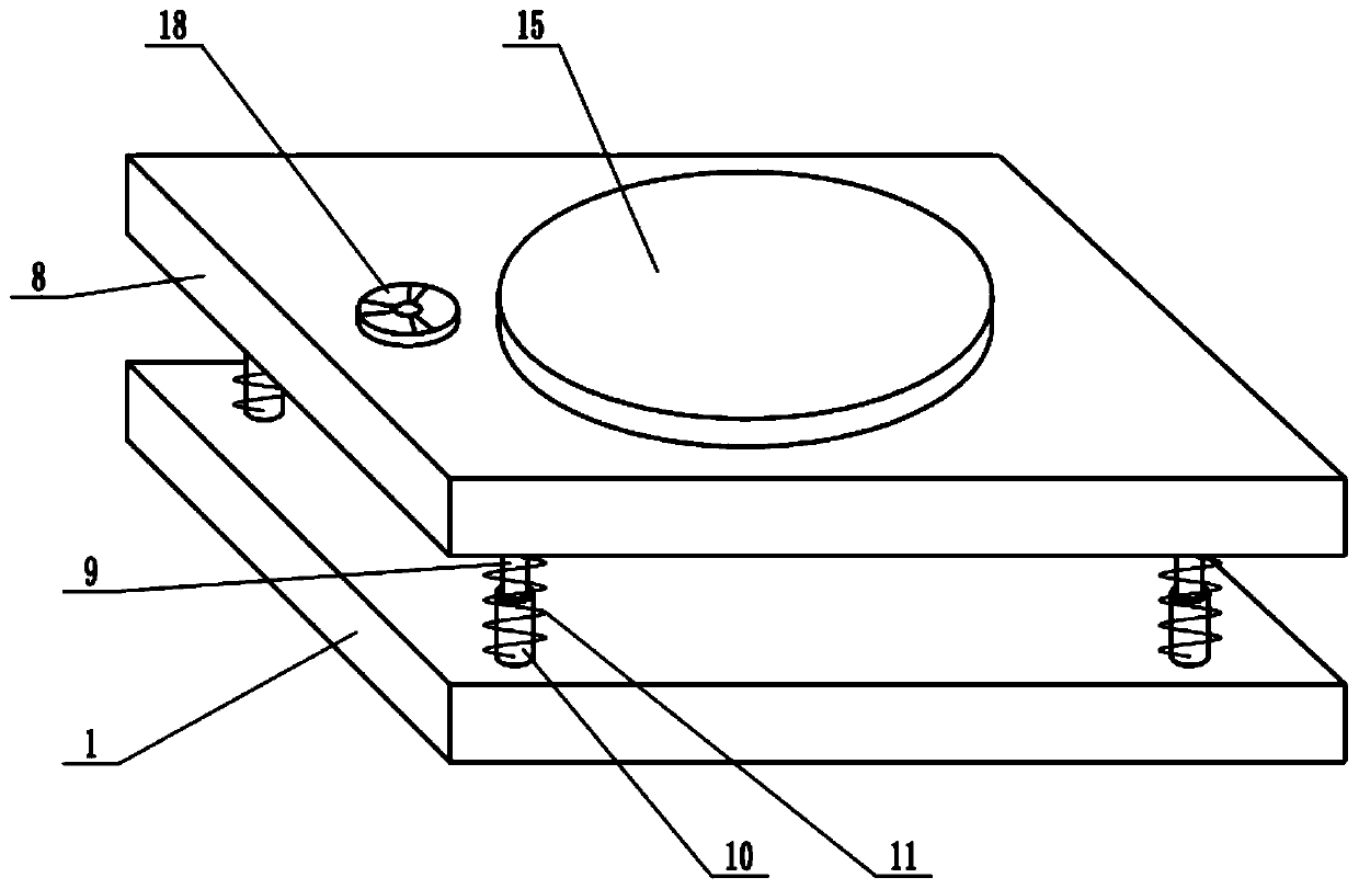
[0021] See Figure 1-3 In the embodiment of the present invention, a shock-absorbing motor that is easy to move includes a base 1, a fixing plate 2, a mounting plate 8 and a mounting frame 12. The lower surface of the base 1 is fixedly connected with a fixing plate 2, and the fixing plates 2 share Two are arranged symmetrically. A support plate 3 is installed at the bottom of the fixed plate 2. The support plate 3 is used to increase the contact area between the device and the ground, thereby improving the stability of the device. A mounting plate 8 is provided above the base 1 , The lower surface of the mounting plate 8 is fixedly connected with a guide rod 9, a sleeve 10 is sleeved under the guide rod 9, and the sleeve 10 is slidably connected to the guide rod 9, and the guide rod 9 can slide up and down in the sleeve 10. The lower end of 10 is fixedly connected with the upper surface of the base 1, a shock-absorbing spring 11 is sleeved on the sleeve 10, th...

Example Embodiment

[0022] Example 2

[0023] On the basis of embodiment 1, a moving mechanism is installed under the base 1. The moving mechanism includes a telescopic mechanism 4, a slider 5, a movable rod 6 and a connecting rod 7, and the side wall of the fixed plate 2 is fixedly connected with the telescopic mechanism 4. The telescopic mechanism 4 is an electro-hydraulic telescopic cylinder. The extension end of the telescopic mechanism 4 is fixedly connected with a slider 5, and the slider 5 is slidably connected to the lower surface of the base 1. The telescopic mechanism 4 is controlled to expand and contract, and the slider 5 can be driven along the base. The lower surface of the base 1 slides left and right, the lower surface of the base 1 is hinged with a movable rod 6, the lower end of the movable rod 6 is equipped with a roller, the lower surface of the slider 5 is hinged with a connecting rod 7, and the lower end of the connecting rod 7 is connected with the movable rod 6. The middle pa...

Example

[0024] Combining Embodiment 1 and Embodiment 2, the working principle of the present invention is: install the motor on the turntable 15 and rotate the turntable 18, and the rotating shaft 16 can be driven by the transmission belt 20 to rotate, thereby driving the turntable 15 to rotate. Adjust the motor according to actual installation requirements. The orientation is very convenient. When it is rotated to a proper position, the turntable 15 is locked by the positioning buckle to keep the turntable 15 and the mounting plate 8 relatively fixed. During the operation of the motor, the shock-absorbing spring 11 and the plate spring 13 can be used In order to reduce the vibration of the device during operation, the effect of reducing noise and protecting the motor is achieved. When the device needs to be moved, the telescopic mechanism 4 is controlled to extend, and the movable rod 6 is driven to rotate in the vertical direction. The roller moves down to make the roller meet the gro...


PUM


Abstract

The invention relates to the technical field of motors, more particularly to a damping motor convenient to move. The motor comprises a base, a fixed plate, a mounting plate and a mounting frame, the lower surface of the base is fixedly connected with the fixed plate; the mounting plate is arranged above the base; the lower surface of the mounting plate is fixedly connected with a guide rod; a sleeve sleeves the lower part of the guide rod; the sleeve is slidably connected with the guide rod; the lower end of the sleeve is fixedly connected with the upper surface of the base; the lower surfaceof the mounting plate is fixedly connected with the mounting frame; a plate spring is fixedly connected to the mounting frame; a turntable is mounted on the upper surface of the mounting plate; a moving mechanism is mounted below the base; by rotating the turntable, the orientation of the motor can be adjusted very conveniently according to actual installation requirements, in the operation process of the motor, a damping spring and a plate spring can play a role in damping, vibration generated during operation of the device is reduced, the effects of reducing noise and protecting the motor are achieved, and the device can be pushed to move conveniently by arranging the liftable rollers.

Description

technical field [0001] The invention relates to the technical field of motors, in particular to a shock-absorbing motor that is easy to move. Background technique [0002] A motor is a device that converts electrical energy into mechanical energy. It uses energized coils to generate a rotating magnetic field and acts on the rotor to form a magnetoelectric force rotating torque. Motors are divided into DC motors and AC motors according to the power used. The motor is mainly composed of a stator and a rotor. The direction of the current-carrying wire in the magnetic field is related to the direction of the current and the direction of the magnetic induction line. The working principle of the motor is that the magnetic field acts on the force of the current to make the motor rotate. [0003] The existing motor vibrates greatly during operation and is inconvenient to move. Contents of the invention [0004] The object of the present invention is to provide a shock-absorbing...

Claims


Application Information

Patent Timeline
IPC IPC(8): H02K5/24H02K5/26
CPCH02K5/24H02K5/26
Inventor 谢玉贤林杰赵兴华
Owner SUPERSOCO INTELLIGENT TECHNOLOGY (SHANGHAI) CO LTD
Why Eureka
Try Eureka