Porous medium seepage visualization device capable of measuring piezoelectric conversion characteristics

A technology of porous media and piezoelectric conversion, applied in measuring devices, suspension and porous material analysis, permeability/surface area analysis, etc., can solve problems such as judgment and research, and achieve beneficial effects

Pending Publication Date: 2020-05-15
CHINA UNIV OF MINING & TECH
0 Cites 1 Cited by

AI-Extracted Technical Summary

Problems solved by technology

[0004] In the existing technology, the generation of potential difference and the in...

Method used

Concretely, in this embodiment, a second positioning device is provided on the liquid outlet piston 18, and the positioning of the position of the liquid inlet piston 5 in the seepage tube 16 can be realized by the second positioning device, and the Ensure the sealing isolation of the liquid inlet piston 5 in the seepage tube 16 .
In the present embodiment, the two ends of seepage pipe 16 are connected with two opposite inner walls of casing 3, can form support to seepage pipe 16 by casing 3, and then guarantee the tightness of seepage pipe 16 in casing 3 stability.
In this embodiment, a first positioning device is provided on the liquid inlet piston 5, and the positioning of the position of the liquid inlet piston 5 in the seepage tube 16 c...

Abstract

The invention discloses a porous medium seepage visualization device capable of measuring piezoelectric conversion characteristics. The porous medium seepage visualization device comprises a box body,a liquid inlet pipe, a liquid outlet pipe, a first isolation device, a second isolation device, a first pressure sensor, a second pressure sensor, a seepage pipe, a first measuring electrode, a second measuring electrode, a liquid inlet piston, a liquid outlet piston and a controller. The seepage pipe is arranged in the box body, and the liquid inlet pipe and the liquid outlet pipe are communicated with the seepage pipe; the first isolation device and the second isolation device are arranged in the seepage pipe; the first measuring electrode, the first pressure sensor, the second pressure sensor and the second measuring electrode are connected with the controller; the seepage pipe is made of a transparent material; a transparent window is arranged on the box body; or the box body is madeof a transparent material. When the porous medium is subjected to a seepage experiment, visual observation can be carried out, and the potential difference is visually observed and measured so that the research on the porous medium is deeper and the utilization of the porous medium is more facilitated.

Application Domain

Permeability/surface area analysis

Technology Topic

VisualizationVisual observation +5

Image

  • Porous medium seepage visualization device capable of measuring piezoelectric conversion characteristics
  • Porous medium seepage visualization device capable of measuring piezoelectric conversion characteristics
  • Porous medium seepage visualization device capable of measuring piezoelectric conversion characteristics

Examples

  • Experimental program(1)

Example Embodiment

[0036] In order to make the objectives, technical solutions, and advantages of the embodiments of the present invention clearer, the technical solutions in the embodiments of the present invention will be described clearly and completely in conjunction with the accompanying drawings in the embodiments of the present invention. Obviously, the described embodiments It is a part of the embodiments of the present invention, not all the embodiments. The components of the embodiments of the present invention generally described and illustrated in the drawings herein may be arranged and designed in various different configurations.
[0037] Therefore, the following detailed description of the embodiments of the present invention provided in the accompanying drawings is not intended to limit the scope of the claimed invention, but merely represents selected embodiments of the present invention. Based on the embodiments of the present invention, all other embodiments obtained by those of ordinary skill in the art without creative work shall fall within the protection scope of the present invention.
[0038] It should be noted that similar reference numerals and letters indicate similar items in the following figures. Therefore, once an item is defined in one figure, it does not need to be further defined and explained in subsequent figures.
[0039] In the description of the present invention, it should be noted that the terms "center", "upper", "lower", "left", "right", "vertical", "horizontal", "inner", "outer", etc. The indicated position or position relationship is based on the position or position relationship shown in the drawings, or the position or position relationship usually placed when the product of the invention is used, only for the convenience of describing the present invention and simplifying the description, rather than indicating or implying The referred device or element must have a specific orientation, be configured and operated in a specific orientation, and therefore cannot be understood as a limitation of the present invention. In addition, the terms "first", "second", "third", etc. are only used for distinguishing description, and cannot be understood as indicating or implying relative importance.
[0040] In addition, the terms "horizontal", "vertical", "overhanging" and other terms do not mean that the component is required to be absolutely horizontal or overhang, but may be slightly inclined. For example, "horizontal" only means that its direction is more horizontal than "vertical", and it does not mean that the structure must be completely horizontal, but can be slightly inclined.
[0041] In the description of the present invention, it should also be noted that the terms "set", "installation", "connected", and "connected" should be interpreted broadly, unless otherwise clearly specified and limited. For example, it may be a fixed connection. It can also be detachably connected or integrally connected; it can be mechanically or electrically connected; it can be directly connected or indirectly connected through an intermediate medium, and it can be the internal communication between two components. For those of ordinary skill in the art, the specific meanings of the above-mentioned terms in the present invention can be understood in specific situations.
[0042] Attached below Figure 1-Figure 3 , A detailed description of some embodiments of the present invention. In the case of no conflict, the following embodiments and features in the embodiments can be combined with each other.
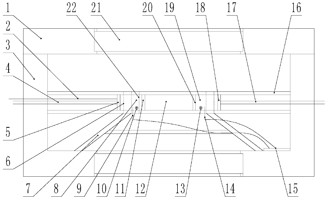
[0043] A porous medium seepage visualization device capable of measuring piezoelectric conversion characteristics, which is characterized by comprising a box body 3, a liquid inlet pipe 4, a liquid outlet pipe 17, a first isolation device 11, a second isolation device 20, and a first pressure sensor 10. The second pressure sensor 13, the seepage tube 16, the first measurement electrode 9, the second measurement electrode 14, the liquid inlet piston 5, the liquid outlet piston 18 and the controller 15; the seepage tube 16 is arranged in the box 3, and the liquid inlet One end of the pipe 4 is arranged outside the box 3, the other end is connected with one end of the seepage pipe 16, one end of the outlet pipe 17 is arranged outside the box 3, and the other end is connected with the other end of the seepage pipe 16; the first isolation device 11 , The second isolation device 20 is arranged in the seepage tube 16, so that the seepage tube 16 is divided into three parts: the first pressure chamber 8, the seepage chamber 12 and the second pressure chamber 19; the liquid inlet piston 5 is slidably arranged in the first In the pressure chamber 8, the inlet pipe 4 communicates with the first pressure chamber 8 through the inlet piston 5; the outlet piston 18 is slidably arranged in the second pressure chamber 19, and the outlet pipe 17 passes through the outlet piston 18 and the second pressure chamber 19 is connected; a first pressure sensor 10 is provided in the first pressure chamber 8, one end of the first measuring electrode 9 is provided in the first pressure chamber 8, and the other end is connected to the controller 15, the first pressure sensor 10 and the controller 15 Signal connection; a second pressure sensor 13 is arranged in the second pressure chamber 19, one end of the second measuring electrode 14 is arranged in the second pressure chamber 19, and the other end is connected to the controller 15, the second pressure sensor 13 and the controller 15 Signal connection; seepage pipe 16 is made of transparent material; box 3 is provided with a transparent window; or, box 3 is made of transparent material.
[0044] In this embodiment, the cover plate 1 of the box 3 is provided with a transparent window 21, and a transparent window 21 is also provided at the bottom. A transparent window 21 may also be provided on the side wall to facilitate the seepage in the box 3. Observe the situation. Specifically, the seepage tube 16 is also set with a transparent material, and when the seepage experiment is performed, the seepage situation can be visually observed.
[0045] In this embodiment, by adjusting the positions of the first isolation device 11 and the second isolation device 20, it can be adapted to different types of porous media and different lengths of the porous media.
[0046] In the seepage experiment, first set the porous medium in the seepage chamber 12 of the seepage tube 16, adjust the space of the first pressure chamber 8 through the liquid inlet piston 5, and adjust the space of the second pressure chamber 19 by the liquid outlet piston 18 After adjustment, when the liquid enters the first pressure chamber 8 through the liquid inlet pipe 4, a certain hydraulic pressure is formed. The liquid in the first pressure chamber 8 enters the seepage chamber 12 through the first isolating device 11 and starts to seep After the liquid passes through the seepage chamber 12, it enters the second pressure chamber 19 through the second isolation device 20, and then is discharged through the liquid outlet pipe 17.
[0047] During the whole seepage process, the pressures in the first pressure chamber 8 and the second pressure chamber 19 are different. The pressure in the first pressure chamber 8 is collected by the first pressure sensor 10. The pressure in the second pressure chamber 19 is Then the pressure difference between the first pressure chamber 8 and the second pressure chamber 19 is judged; the second pressure sensor 13 is used for collection. And through the first measuring electrode 9 and the second measuring electrode 14, the flow potential in the first pressure chamber 8 and the second pressure chamber 19 are measured respectively.
[0048] In this embodiment, the first isolation device 11 is an isolation net or an isolation plate with a plurality of communication holes, which can flow the liquid in the first pressure chamber 8 into the seepage chamber 12 to perform a seepage experiment.
[0049] In this embodiment, the seepage tube 16 is formed by splicing two sections, and the splicing interface 22 is located once the first isolation device 11 is away from the seepage cavity 12.
[0050] In use, first connect the liquid outlet piston 18 to the liquid outlet pipe 17, install the liquid outlet piston 18 in one of the seepage pipes 16, and install the second isolating device 20 in the seepage pipe 16, and then install the porous medium Fill in the seepage pipe 16, and then install the first isolation device 11 into the seepage pipe 16, connect another section of the seepage pipe 16 to it, and finally, install the liquid inlet piston 5 and the liquid inlet pipe 4 in another One section of seepage pipe 16 is sufficient.
[0051] In other words, the installation process figure 1 In the structure shown, they are installed in sequence from right to left.
[0052] In a preferred embodiment of the present invention, the seepage tube 16 is a heat shrinkable tube.
[0053] In this embodiment, the seepage tube 16 is set as a heat shrinkable tube, which can realize the overall installation more conveniently.
[0054] In a preferred embodiment of the present invention, a first positioning device is provided on the liquid inlet piston 5 for positioning the position of the liquid inlet piston 5 in the seepage pipe 16.
[0055] In this embodiment, a first positioning device is provided on the liquid inlet piston 5. The first positioning device can not only realize the positioning of the position of the liquid inlet piston 5 in the seepage pipe 16, but also ensure that the liquid inlet piston 5 is in position. The sealing isolation in the seepage pipe 16.
[0056] Specifically, in this embodiment, a second positioning device is provided on the liquid outlet piston 18. The second positioning device can not only realize the positioning of the position of the liquid inlet piston 5 in the seepage pipe 16, but also ensure the liquid inlet The piston 5 is sealed and isolated in the seepage pipe 16.
[0057] In this embodiment, the structure of the first positioning device and the second positioning device may be the same or different, as long as the positioning and sealing functions of the liquid inlet piston 5 and the liquid outlet piston 18 can be realized.
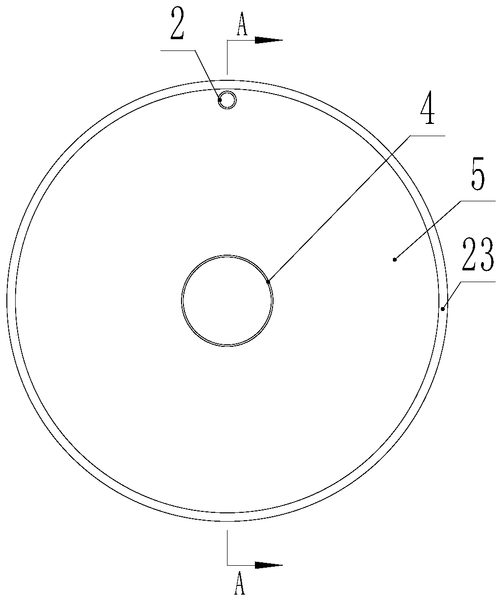
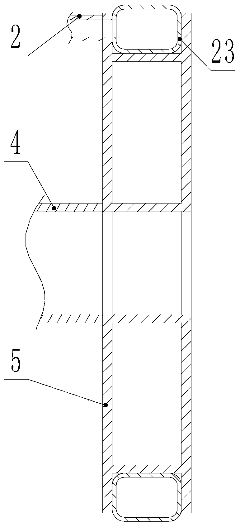
[0058] In a preferred embodiment of the present invention, the first positioning device includes an expansion loop 23, a power pump, and a connecting pipe 2. The power pump communicates with the expansion loop 23 through the connecting pipe 2 for inputting expansion into the expansion loop 23. medium.
[0059] Specifically, in this embodiment, the expansion ring tube 23 is arranged on the outer wall of the liquid inlet piston 5, and the positioning and sealing of the liquid inlet piston 5 in the seepage tube 16 is realized by the expansion of the expansion ring tube 23, which ensures the inlet The liquid piston 5 will not freely slide in the seepage tube 16 and can prevent the liquid entering the seepage tube 16 from flowing out from one side of the liquid inlet piston 5.
[0060] More specifically, in this embodiment, the expansion loop tube 23 is connected to the power pump through the communication tube 2, and the power pump is used to input the expansion medium into the expansion loop tube 23, thereby causing the expansion loop tube 23 to expand, and then the liquid inlet piston 5 is fixed inside the seepage pipe 16.
[0061] In this embodiment, when the first positioning device is required for positioning, it is sufficient to expand the medium into the expansion loop 23 through the power pump. When it is necessary to adjust the first pressure chamber 8 by moving the liquid inlet piston 5, The power pump can extract the expansion medium in the expansion loop 23.
[0062] Specifically, in a preferred embodiment of the present invention, the expansion medium is gas or liquid.
[0063] More specifically, the liquid is water.
[0064] In a preferred embodiment of the present invention, the material of the expansion ring tube 23 is rubber.
[0065] It should be pointed out that the material of the expansion ring tube 23 can be rubber, but it is not limited to rubber. It can also be made of other elastic materials, such as plastic. That is, as long as it can expand, It is sufficient to realize the positioning of the liquid inlet piston 5 and the sealing of the seepage pipe 16.
[0066] In a preferred embodiment of the present invention, a control valve is provided on the communication pipe 2.
[0067] Through the setting of the control valve, the expansion medium in the expansion loop 23 can be prevented from returning, thereby ensuring the stability of the positioning of the liquid inlet piston 5.
[0068] In this embodiment, the control valve may be a control valve with only two states of on and off, or a control valve with a flow control function.
[0069] In a preferred embodiment of the present invention, the two ends of the seepage pipe 16 are respectively connected to two opposite inner walls of the box 3.
[0070] In this embodiment, the two ends of the seepage tube 16 are connected to two opposite inner walls of the box 3, and the seepage tube 16 can be supported by the box 3 to ensure the stability of the seepage tube 16 in the box 3.
[0071] Specifically, in this embodiment, the two ends of the seepage tube 16 and the box body 3 can be abutted or clipped, as long as the seepage tube 16 can be arranged on the inner wall of the box body 3 to realize the box The body 3 supports the seepage pipe 16 only.
[0072] In another preferred embodiment of the present invention, a support is provided in the box 3, and the seepage pipe 16 is provided on the support.
[0073] Through the setting of the support, the support for the middle of the seepage pipe 16 is realized, and the stability of the seepage pipe 16 in the box 3 can be further increased, and the accuracy of the seepage experiment can be ensured.
[0074] Specifically, the support includes a leg 7, a connecting rod, and a fixing ring 6. The legs 7 are connected by a connecting rod to form a whole. The fixing ring 6 is arranged on the upper part of the leg 7 to fix the seepage tube 16 in On the outrigger 7.
[0075] It should be pointed out that the arrangement of the support can be the above-mentioned way, it can also be other ways, as long as it can realize the fixation of the seepage pipe 16.
[0076] The beneficial effects of the embodiments of the present invention are:
[0077] The porous media seepage visualization device that can measure the piezoelectric conversion characteristics can perform visual observations during the seepage experiment of porous media, and at the same time perform intuitive observation and measurement of the potential difference, making the research on porous media more in-depth and more beneficial Utilization of porous media.
[0078] The above are only preferred embodiments of the present invention and are not used to limit the present invention. For those skilled in the art, the present invention can have various modifications and changes. Any modification, equivalent replacement, improvement, etc., made within the spirit and principle of the present invention shall be included in the protection scope of the present invention.

PUM

no PUM

Description & Claims & Application Information

We can also present the details of the Description, Claims and Application information to help users get a comprehensive understanding of the technical details of the patent, such as background art, summary of invention, brief description of drawings, description of embodiments, and other original content. On the other hand, users can also determine the specific scope of protection of the technology through the list of claims; as well as understand the changes in the life cycle of the technology with the presentation of the patent timeline. Login to view more.

Similar technology patents

Liquid split charging device for microbiological inspection

PendingCN114790415Aconducive to useImprove adaptability
Owner:贵阳康养职业大学

Catalyst for reaction for preparing 1,3-butadiene from ethanol, preparation and applications thereof

ActiveCN111217656Aconducive to useInhibit the occurrence of side effects
Owner:DALIAN INST OF CHEM PHYSICS CHINESE ACAD OF SCI

Wall-hanging type airing bath towel rack

InactiveCN109044161Aeasy to dryconducive to use
Owner:苏州众曼精密机械有限公司

Adjustable neck protection pillow

InactiveCN105902087AEasy to adjustconducive to use
Owner:NANTONG RICHISLAND BEDDING DEV CO LTD

LED landscape lamp capable of killing mosquitoes

InactiveCN111642477Aconducive to useImprove the decorative effect
Owner:中山市荣浩电子商务有限公司

Classification and recommendation of technical efficacy words

  • conducive to use

Self-cleaning hand mower

InactiveCN105493735ASave time and costconducive to use
Owner:ANHUI HUAFENG AGRI PROD PROFESSIONAL COOP

Fully-automatic deburring device

InactiveCN112720102AGuarantee air qualityconducive to use
Owner:汤孝波

Door capable of reminding deformation

ActiveCN109356485Aeasy to renewconducive to use
Owner:陈果

Preparation method of oxygen supply agent for promoting lactic acid bacteria to rapidly consume sugar without changing ventilation control strategy

ActiveCN110921632Aconducive to useSpeed ​​up the fermentation process
Owner:河南金丹乳酸科技股份有限公司

Waterproof structure of new energy automobile charging pile

ActiveCN112993656Aconducive to use
Owner:长春工业大学人文信息学院
Why Eureka
Try Eureka