
Interference source direction finding method based on sidelobe cancellation coefficient

A technology of interference source and side lobe, which is applied in directions such as direction finders using radio waves, radio wave measurement systems, and radio wave direction/bias determination systems. problem, to achieve the effect of a small amount of calculation

Pending Publication Date: 2020-05-19
中国船舶集团有限公司第七二四研究所
View PDF3 Cites 0 Cited by
  • Summary
  • Abstract
  • Description
  • Claims
  • Application Information

AI Technical Summary

Benefits of technology

This patented technology allows for better performance without adding extra equipment or requiring more computational power than necessary. It also saves on memory space by searching through specific frequency bands instead of all that are needed.

Problems solved by technology

This patented technology uses two main techniques: one involves measuring the distance between an object being observed (the target) and another object that may also have its own radioactive material or harmful effects - called cluttering signals. Passively-scanned ratios involve taking multiple measurements with each measurement taken over at least once while avoiding any false alarms caused by external factors like background noise. These techniques require fewer calculations compared to current methods such as space spectral analysis and signal processing. However, they still take longer because these techniques work well when there're few objects around them but cannot distinguish between realistically important ones and potential attacks.

Method used


Image

  • Interference source direction finding method based on sidelobe cancellation coefficient
  • Interference source direction finding method based on sidelobe cancellation coefficient
  • Interference source direction finding method based on sidelobe cancellation coefficient

Examples


Embodiment

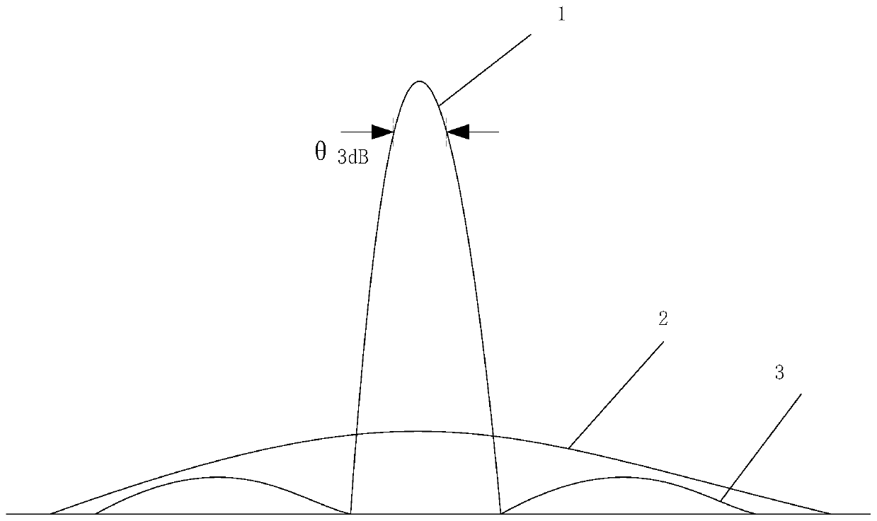
[0017] Assume that the radar azimuth and elevation wave widths are both 3.2°, and the interference direction is 30.2° in azimuth and 9.8° in elevation. Process flow of the present invention is:

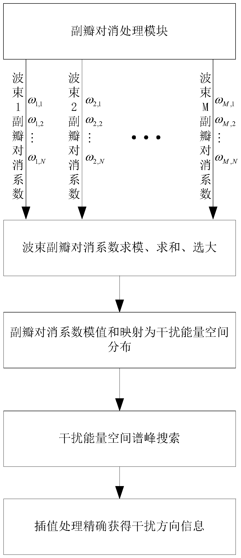
[0018] 1. Receive N complex sidelobe cancellation coefficients corresponding to the simultaneous M beams from the sidelobe cancellation module, where:

[0019] The cancellation coefficient of the N sidelobes of the first beam is: ω 1,1 ,…,ω 1,N ,

[0020] The cancellation coefficient of the N sidelobe of the Mth beam is: ω M,1 ,…,ω M,N ;

[0021] 2. Calculate the modulus sum of the M beam sidelobe cancellation coefficients in each period:

[0022] W k =abs(ω k,1 )+abs(ω k,2 )+…+abs(ω k,N )

[0023] where 1≤k≤M;

[0024] 3. The modulus and W of the radar sidelobe cancellation coefficient are inversely proportional to the difference between the incident direction of interference and the beam pointing angle, and the difference between the incident direction of interference an...


PUM


Abstract

The invention provides an interference source direction finding method based on a sidelobe cancellation coefficient. The method comprise a receiving a sidelobe cancellation coefficient calculated by aradar sidelobe cancellation module, calculating the sum of cancellation coefficient modulus of each wave position sidelobe, establishing mapping between the sum of cancellation coefficient modulus ofeach wave position sidelobe and interference energy spatial distribution, performing spatial domain spectral peak search on an interference energy spatial spectrum, and performing spline interpolation processing for three times near a spectral peak to obtain more accurate interference orientation and elevation angle.

Description


Claims


Application Information

Patent Timeline
Owner 中国船舶集团有限公司第七二四研究所
Learn More