Feature modeling in a finite element model

a finite element model and feature technology, applied in the field of methods for modeling physical systems using finite element analysis, can solve the problems of difficult to force the function to approximate changes, difficult to accurately simulate the behavior of the model, and more complicated means of modeling physical systems

Active Publication Date: 2005-09-06
LANDMARK GRAPHICS
View PDF61 Cites 75 Cited by
  • Summary
  • Abstract
  • Description
  • Claims
  • Application Information

AI Technical Summary

Benefits of technology

[0008]One or more of the problems outlined above may be solved by the various embodiments of the present invention. Broadly speaking, the invention comprises a method for simulating a physical system using a finite element model which comprises at least two distinct models corresponding to distinct regions within the modeled system.

Problems solved by technology

One of the more complicated means to model physical systems is through the use of finite element analysis.
Conventional finite element models, however, have certain limitations which prevent them from accurately simulating the behavior of the physical systems which the model.
It may be very difficult to force these functions to approximate changes in the properties which occur very abruptly as a result of geological features within the reservoir.
Even if the mathematical function can be adapted to represent the respective values for the property at the boundary between the two layers, such a function would typically be very complex and would require a great deal of computational resources.

Method used


Image

  • Feature modeling in a finite element model
  • Feature modeling in a finite element model
  • Feature modeling in a finite element model

Examples


Embodiment Construction

[0022]A preferred embodiment of the invention is described below. It should be noted that this and any other embodiments described below are exemplary and are intended to be illustrative of the invention rather than limiting.

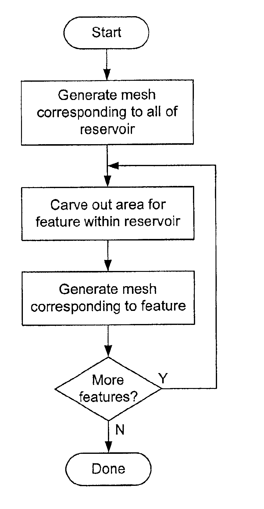
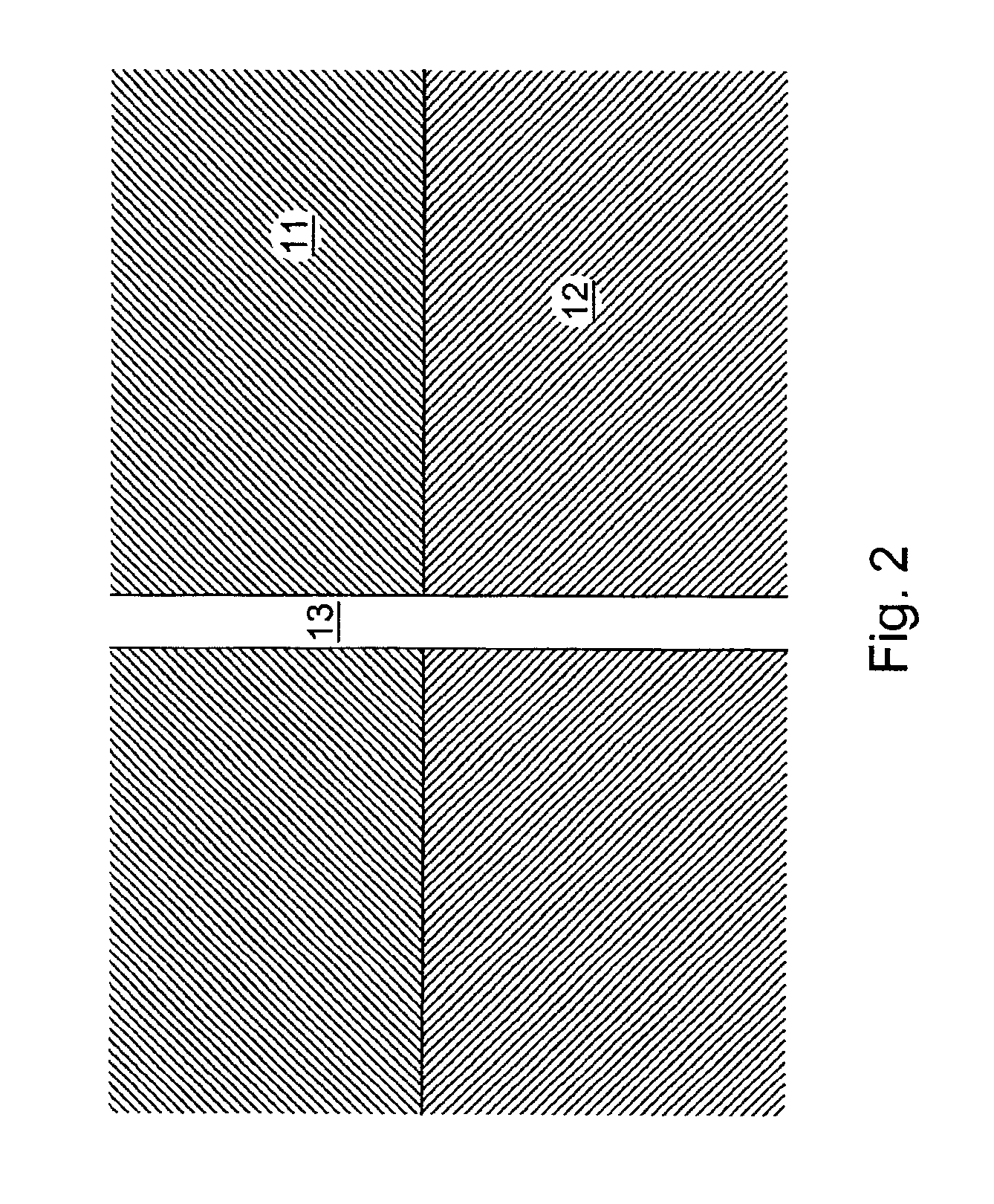
[0023]Generally speaking, the present invention comprises a method for simulating systems using a finite element modeling, as well as computer applications which embody the method and computers which are configured to perform the method. The method involves the definition of multiple, distinct finite element models which represent corresponding regions within the modeled system. Each of these finite only models comprises a set of nodes at which values are defined for various properties. For nodes which lie on boundaries between models, there are a plurality of values corresponding to a given property, wherein each of the values corresponds to a different one of the models. Each of the models is solved separately, using the values for each property which correspo...


PUM


Abstract

A method for simulating a physical system using finite element techniques, wherein two or more distinct models corresponding to distinct regions within the modeled system are solved, each with a corresponding evaluator. Nodes which lie on the boundaries between the models may have different values corresponding to the different models. When a particular model is solved, the evaluator for that model is used to obtain the appropriate values for each of these common nodes. In one embodiment, a first model is defined, then a region corresponding to a particular feature within the system is carved out of it. A finite element model corresponding to the feature is then inserted into the region. The finite elements may be adapted to share nodes on the boundaries between them.

Description

RELATED APPLICATIONS[0001]This application claims priority under 35 U.S.C. §119(e) to U.S. patent application Ser. No. 60 / 215,697 entitled “Method and System for Oil Reservoir Simulation and Modeling” by Stephen R. Kennon, Kok Thye Lim, Scott A. Canaan, Steven B. Ward, Stuart W. Pond, Jr. and Edward J. Barragy, filed Jun. 29, 2000, which is incorporated by reference as if set forth in its entirety herein.TECHNICAL FIELD OF THE INVENTION[0002]This invention relates generally to methods for modeling physical systems using finite element analysis and, more specifically, to methods for modeling features of the physical systems, such as fractures in a geological structure, for which one or more properties change at the boundaries between these features and the surrounding regions of the physical system.BACKGROUND OF THE INVENTION[0003]Physical systems can be modeled mathematically to simulate their behavior under certain conditions. There are a wide variety of means to model these system...

Claims


Application Information

Patent Timeline
Patent Type & Authority Patents(United States)
IPC IPC(8): G01V11/00G06T17/20G06T17/50G06F17/13E21B44/00G06F17/16G06F17/50G06F19/00G06T17/05
CPCG01V11/00G06F17/5004G06F17/5018G06T17/05G06T17/20G06F30/13G06F30/23
Inventor KENNON, STEPHEN R.WARD, STEVEN B.
Owner LANDMARK GRAPHICS
Why Eureka
Try Eureka