Photovoltaic power station configuration method and device

A photovoltaic power station and photovoltaic group technology, applied in photovoltaic power stations, photovoltaic power generation, photovoltaic modules, etc., can solve the problems of large parallel mismatch loss, large voltage difference, and affecting the power generation of photovoltaic power stations, so as to improve power generation efficiency and reduce parallel connection Effect of Mismatch Loss

Inactive Publication Date: 2020-05-19
HEFEI SUNGROW RENEWABLE ENERGY SCI & TECH CO LTD
View PDF5 Cites 4 Cited by
  • Summary
  • Abstract
  • Description
  • Claims
  • Application Information

AI Technical Summary

Problems solved by technology

However, this method ignores the temperature difference between the strings and the voltage difference caused by the different shadows between the strings, so that there is a large volt

Method used


Image

  • Photovoltaic power station configuration method and device
  • Photovoltaic power station configuration method and device
  • Photovoltaic power station configuration method and device

Examples


Embodiment 1

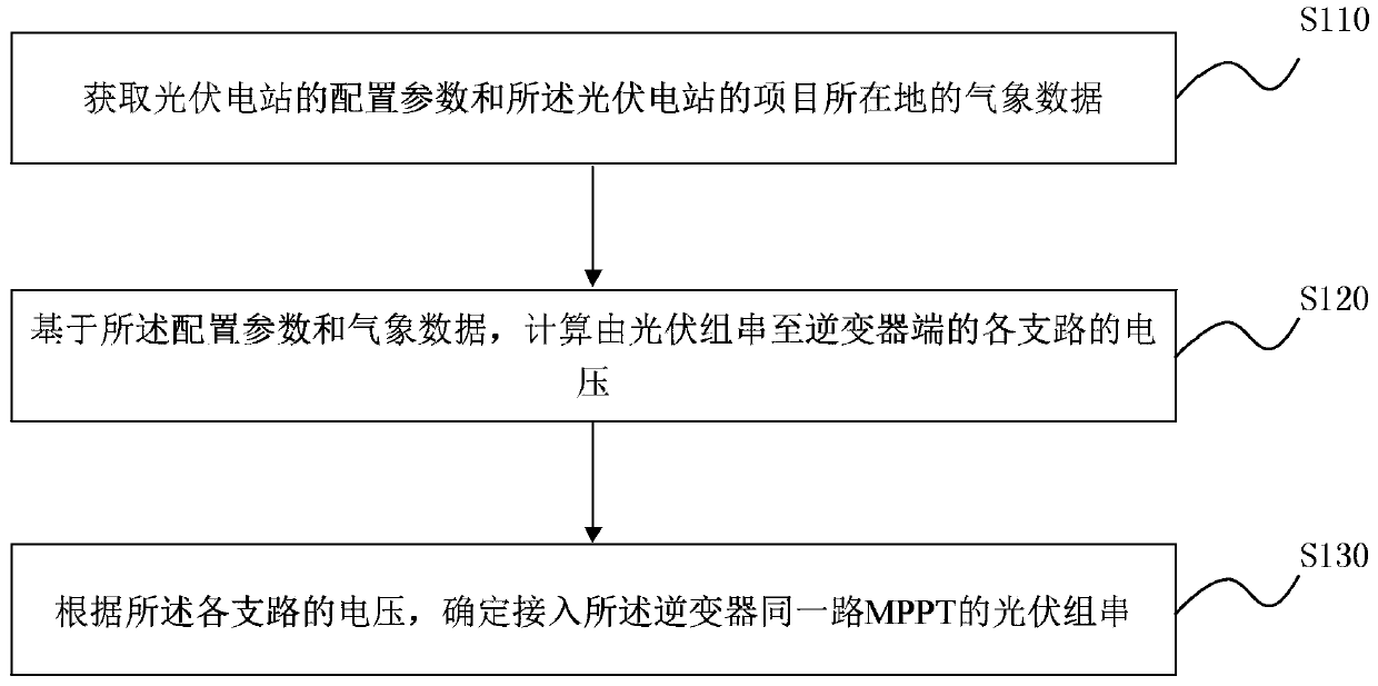
[0020] figure 1 It is a flow chart of a photovoltaic power station configuration method provided by Embodiment 1 of the present invention. This embodiment can be applied to optimize the configuration of photovoltaic power stations to improve power generation efficiency. In order to improve the operating efficiency of the photovoltaic power station, optimize the connection loss. The method may be performed by an apparatus for determining a parallel mismatch loss, for example, performed by a computing device configured with a processor, and the method specifically includes:

[0021] S110. Obtain configuration parameters of the photovoltaic power station and meteorological data of the project location of the photovoltaic power station.

[0022] Among them, the configuration parameters of the photovoltaic power station include the longitude and latitude of the project location, module size, electrical parameters, inverter parameters, module inclination angle, and front-to-back sp...

Embodiment 2

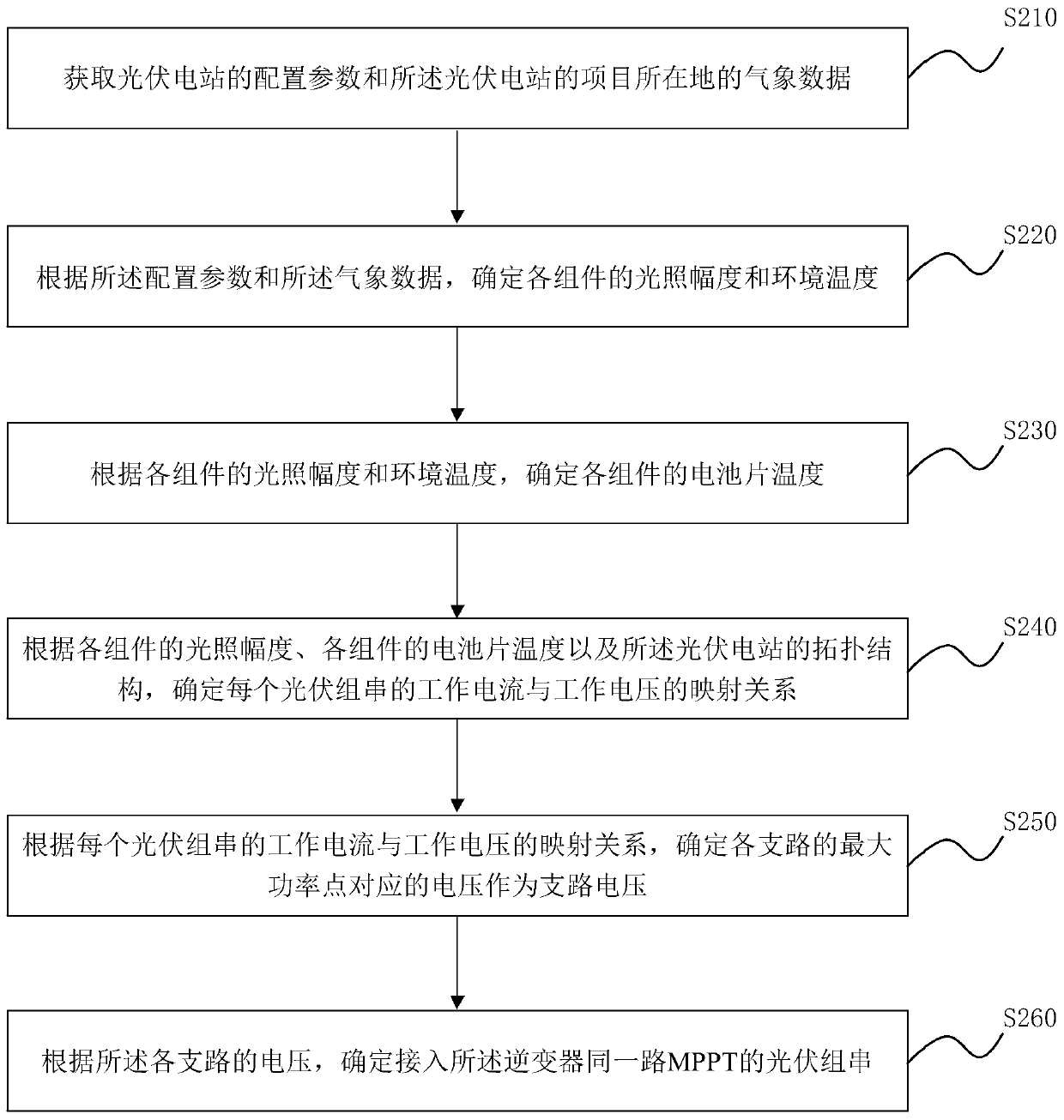
[0036] figure 2 It is a flow chart of an optimized photovoltaic power plant configuration method provided by Embodiment 2 of the present invention. This embodiment optimizes the calculation of the voltage of each branch from the photovoltaic string to the inverter terminal on the basis of the above embodiments. The method specifically includes:

[0037] S210. Obtain configuration parameters of the photovoltaic power station and meteorological data of the project location of the photovoltaic power station.

[0038] S220. Determine the illumination amplitude and ambient temperature of each component according to the configuration parameters and the meteorological data.

[0039] S230. Determine the cell temperature of each component according to the illumination amplitude of each component and the ambient temperature.

[0040] Among them, according to the illumination amplitude and ambient temperature of each component, the cell temperature of each component is determined base...

Embodiment 3

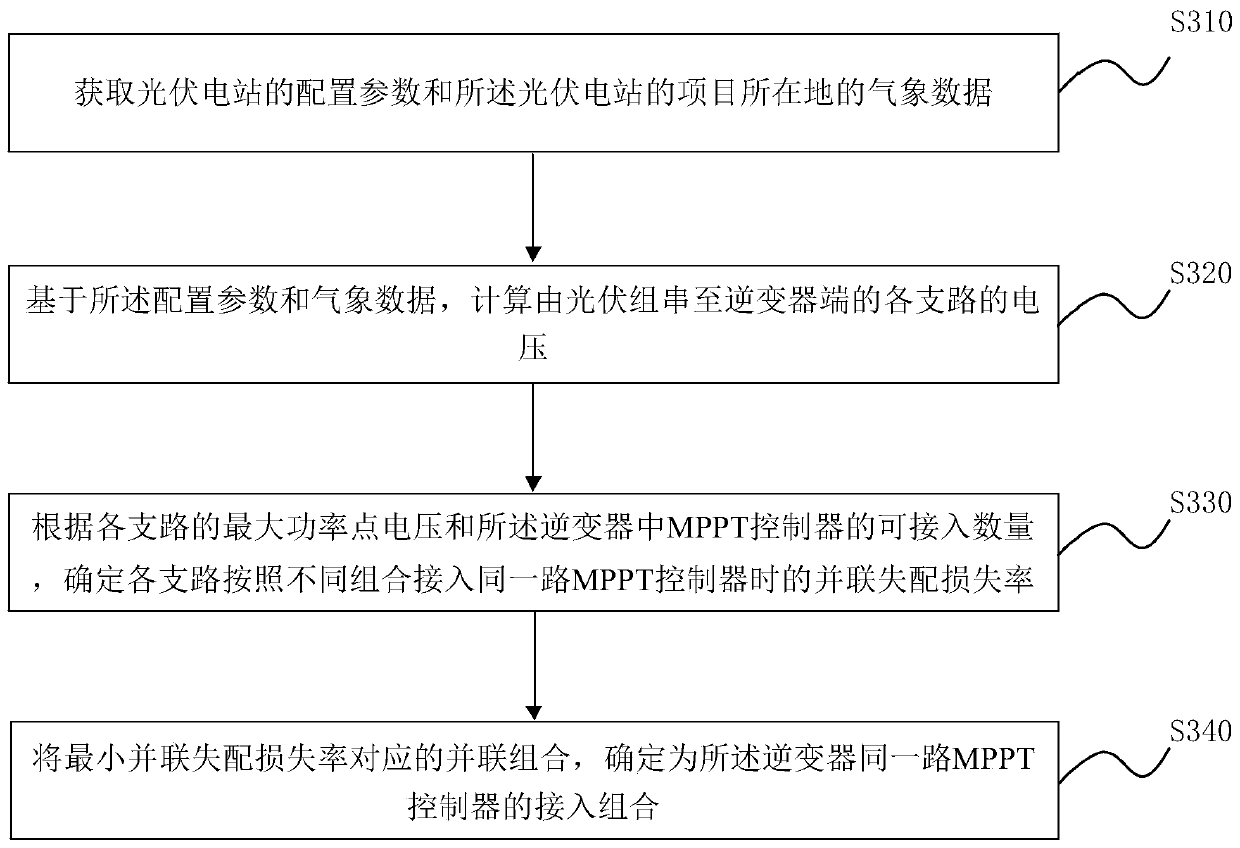
[0092] image 3 It is a flow chart of an optimized photovoltaic power plant configuration method provided by the embodiment of the present invention. This embodiment optimizes the method of determining the photovoltaic strings connected to the same MPPT of the inverter on the basis of the above embodiments. The method specifically includes:

[0093] S310. Obtain configuration parameters of the photovoltaic power station and meteorological data of the project location of the photovoltaic power station.

[0094] S320. Based on the configuration parameters and meteorological data, calculate the voltage of each branch from the photovoltaic string to the inverter.

[0095] Wherein, the voltage of each branch refers to the maximum power point voltage of each branch. The maximum power point voltage of each branch is calculated based on the maximum power point voltage of each component based on the topological structure of the photovoltaic power station. The calculation process is s...


PUM


Abstract

The embodiment of the invention discloses a photovoltaic power station configuration method and device. The photovoltaic power station configuration method comprises the following steps: acquiring configuration parameters of a photovoltaic power station and meteorological data of a project location of the photovoltaic power station; calculating the voltage of each branch from a photovoltaic stringto an inverter end based on the configuration parameters and the meteorological data; and determining photovoltaic strings accessed to the same MPPT of the inverter according to the voltage of each branch. Based on the configuration parameters and the meteorological data, the voltage of each branch is calculated, and the voltage actually output by different branches due to shadow shielding and temperature difference can be determined; the output voltages of different branches are compared, and the branches with the highest output voltage similarity are connected to the same MPPT, so that theproblem that the photovoltaic power station generates large parallel mismatch loss due to the fact that branches with large output voltage difference are connected in parallel without considering shadow shielding and temperature difference at present is solved, the parallel mismatch loss of the photovoltaic power station is reduced, and the power generation efficiency of the photovoltaic power station is improved.

Description

technical field [0001] Embodiments of the present invention relate to photovoltaic power generation technology, and in particular to a method and device for configuring a photovoltaic power station. Background technique [0002] At present, in the design process of photovoltaic power plants, only the line voltage drop of each photovoltaic string is restricted, that is, the strings with the same line voltage drop are connected to the same MPPT, so as to reduce the parallel mismatch loss. However, this method ignores the temperature difference between the strings and the voltage difference caused by the different shadows between the strings, so that there is a large voltage difference between the strings actually connected to the same MPPT, and a large parallel loss occurs. Distribution loss affects the power generation of photovoltaic power plants. Contents of the invention [0003] Embodiments of the present invention provide a method and device for configuring a photovol...

Claims


Application Information

Patent Timeline
IPC IPC(8): H02J3/38H02S10/00
CPCH02S10/00Y02E10/50
Inventor 陈朋朋王忠杨宗军余婷婷
Owner HEFEI SUNGROW RENEWABLE ENERGY SCI & TECH CO LTD
Why Eureka
Try Eureka