
Decoding method and decoding device

A decoding method and technology of a decoding device, which can be applied to other decoding technologies, encoding, code conversion, etc., can solve the problems of poor system transmission capacity and low FEC decoding performance, and achieve improved accuracy, improved accuracy, and improved system transmission capacity. Effect

Active Publication Date: 2022-04-22
HUAWEI TECH CO LTD
View PDF9 Cites 0 Cited by
  • Summary
  • Abstract
  • Description
  • Claims
  • Application Information

AI Technical Summary

Problems solved by technology

Therefore, in the PS-QAM system, there is no correlation between FEC decoding and PS decoding, resulting in low FEC decoding performance and poor system transmission capability

Method used


Image

  • Decoding method and decoding device
  • Decoding method and decoding device
  • Decoding method and decoding device

Examples


example 2

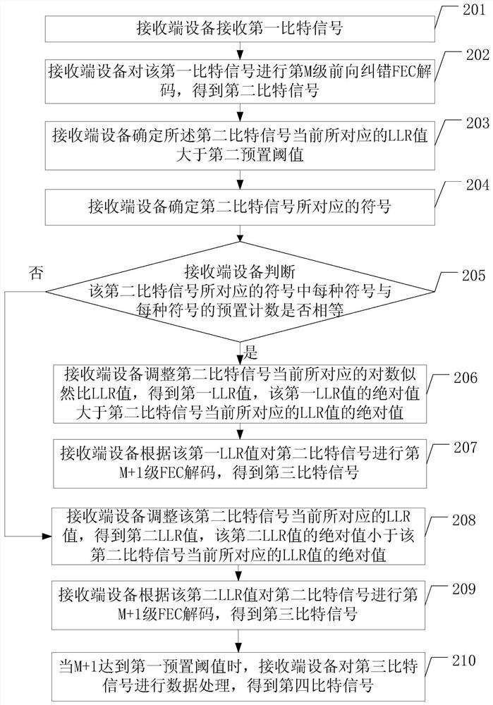
[0047] The receiving end device determines the second bit signal according to the LLR value corresponding to the second bit signal, and then determines the symbol corresponding to the second bit signal. Specifically, the receiving end device may obtain the symbol corresponding to the second bit signal through BL inverse mapping. Example 1: The LLR values ​​corresponding to the second bit signal are 1.38, 0.4, 2.2, -2.2, -1.38 respectively, then the receiving end device can determine that the second bit signal is 1, 1, 1, 0, 0 respectively; and this When the bit "1" is mapped to the symbol "1", and the bit "0" is mapped to the symbol "3", then it can be known that the symbols corresponding to the second bit signal are 1, 1, 1, 3, 3. Example 2: The LLRs corresponding to the second bit signal are 1.38, 0.4, 2.2, -2.2, -1.38, 0.5, 2, -1.38, -0.5, -1 respectively, then the receiving end device can determine that the second bit signal is 1 ,1,1,0,0,1,1,0,0,0 At this time, the bit "...


PUM


Abstract

The embodiment of the present application discloses a decoding method for improving FEC decoding performance and system transmission capability. The method in the embodiment of the present application includes: the receiving end device receives the first bit signal; the receiving end device performs M-level forward error correction FEC decoding on the first bit signal to obtain the second bit signal, where M is a positive integer greater than zero ; The receiving end device verifies the second bit signal to obtain a first verification result; the receiving end device performs the M+1th level on the second bit signal according to the first verification result FEC decoding to obtain a third bit signal; when M+1 reaches the first preset threshold, the receiving end device performs data processing on the third bit signal to obtain a fourth bit signal, and the fourth bit signal is used Obtain the service data transmitted by the sending end device at the receiving end device.

Description

technical field [0001] The present application relates to communication technologies, and in particular to a decoding method and a decoding device. Background technique [0002] With the increasing demand for mobile Internet, 4K / 8K video technology and virtual reality (virtual reality, VR) video technology continue to develop, therefore, it is necessary to provide a larger-capacity optical transmission network to meet the increasing user demand. [0003] Currently, a probabilistic shaping / shaped quadrature amplitude modulation (PS-QAM) system is used to improve spectral efficiency and transmission capability. In the PS-QAM system, the transmitting end converts the bit stream into an optical signal for transmission, while the receiving end decodes the optical signal into a bit signal. The sending end performs probabilistic shaping / shaped (PS) coding on the bit signal, where PS coding includes distribution matching (distribution matching, DM) coding and binary labeling (binar...

Claims


Application Information

Patent Timeline
Patent Type & Authority Patents(China)
IPC IPC(8): H04L1/00H04L65/60H04N7/22
CPCH04L1/0045H04L1/005H04L65/60H04N7/22H04L1/0047H03M13/1111H03M13/3905H03M13/4138H03M13/63H03M13/6325H03M13/3746H04L1/0042H03M13/45
Inventor 黄远达夏斌
Owner HUAWEI TECH CO LTD
Learn More