Check patentability & draft patents in minutes with Patsnap Eureka AI!

A variable-area foot plate

A foot plate and variable technology, applied in cranes and other directions, can solve the problems of inability to take into account the improvement of bearing capacity and limited space storage, and achieve the effects of convenient storage, convenient switching and simple operation.

Active Publication Date: 2021-08-13
XUZHOU HEAVY MASCH CO LTD
View PDF5 Cites 0 Cited by
  • Summary
  • Abstract
  • Description
  • Claims
  • Application Information

AI Technical Summary

Problems solved by technology

When the foot plate is stored, a small-area foot plate is used; when the foot plate is loaded, a large-area foot plate is used, so as to solve the problem that the existing solutions cannot take into account the contradiction between the improvement of the carrying capacity and the limited space storage

Method used


Image

  • A variable-area foot plate
  • A variable-area foot plate
  • A variable-area foot plate

Examples


Embodiment 1

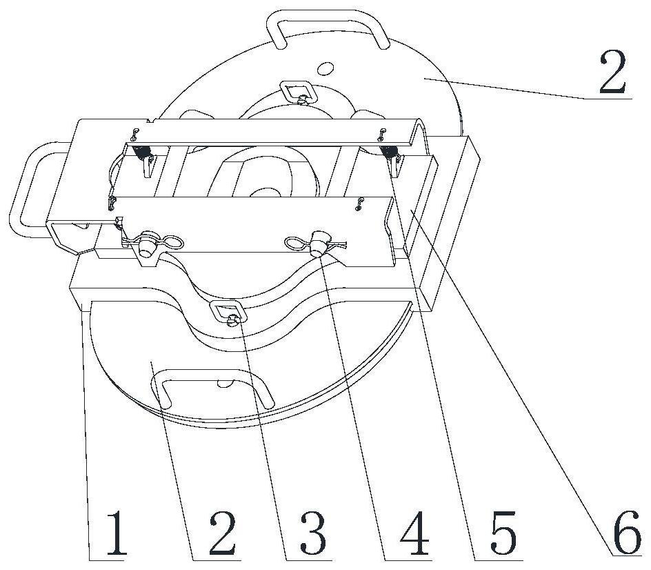
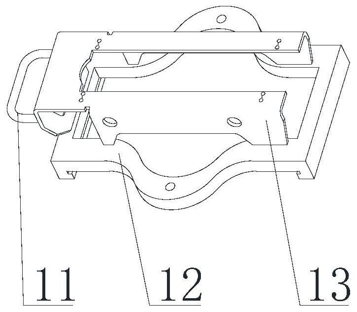
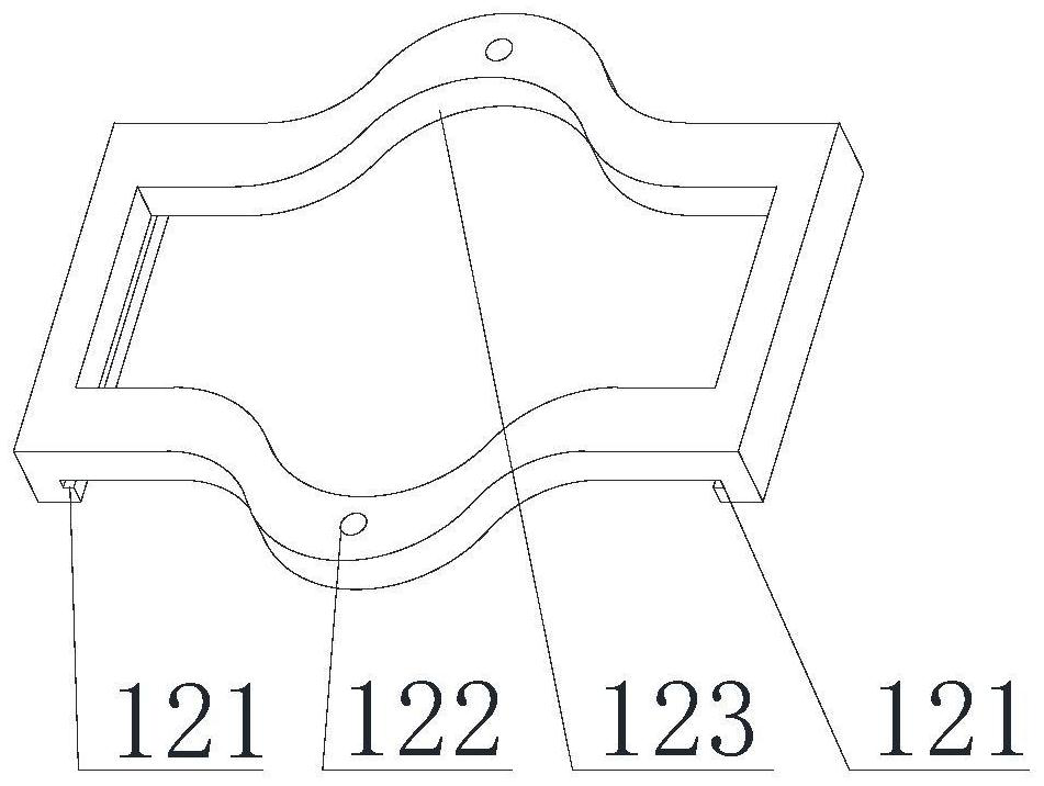
[0036] Such as Figure 1-9 As shown, the present invention provides a variable-area foot plate, including a support 1, a support plate 2, a support block 6, a first pin structure 3, a second pin structure 4 and a spring 5, the support 1 Including a support handle 11, a base 12 and a support base 13; the support handle 11 is arranged on one side of the support base 13 for storing the foot plate; the support base 13 is arranged on the base 12; the base 12 It includes an installation groove 121, a first support pin hole 122 and an accommodation cavity 123; the installation groove 121 is used to assemble the support plate 2, the first support pin hole 122 is used to assemble the first pin structure 3, and the accommodation cavity 123 is used for assembling support block 6. The support seat 13 includes a spring mounting hole 131, a second support pin hole 132 and a chute 133; the spring mounting hole 131 is used for assembling the spring 5, and the second support pin hole 132 is u...

Embodiment 2

[0043] Such as figure 1 As shown, the present invention provides an area-variable support plate, which includes a support 1, a support plate 2, a support block 6, a first pin structure 3, a second pin structure 4 and a spring 5, and the support 1 is a support leg The frame of the tray plays the role of storage operation of the foot tray and installation of other parts, such as Figure 2~4 shown. figure 2 It is the detailed structure of the support 1, and the support 1 includes a support handle 11, a base 12 and a support seat 13, and the support handle 11 is used to store the foot plate. base 12 as image 3 As shown, it includes a mounting groove 121, a first support pin hole 122 and an accommodating cavity 123. Wherein the mounting groove 121 is used for assembling the support plate 2, the first bearing pin hole 122 is used for assembling the first pin structure 3, and the accommodating cavity 123 is used for assembling the support block 6. Support seat 13 such as Figu...


PUM


Abstract

The invention belongs to the field of construction machinery, and specifically relates to an area-variable foot plate, which includes a support, a first pin structure, and a second pin structure; the support is provided with a support plate and a support block, and the first A pin shaft structure is arranged on the support plate to limit the position of the support plate in different states; the second pin structure is installed on the support to limit the position of the hydraulic cylinder; the support plate A first pin hole and a second pin hole are provided; the first pin hole and the second pin hole are used to install the first pin structure, and the first pin hole corresponds to the second state of the foot plate The position of the first pin shaft structure at the same time, the second pin shaft hole corresponds to the position of the first pin shaft structure at the first state of the foot plate. The foot plate structure can realize the change of the supporting area of ​​the foot plate, so as to solve the contradiction between the improvement of the bearing capacity and the storage in the limited space in the existing solutions.

Description

technical field [0001] The invention belongs to the field of engineering machinery, and in particular relates to an area-variable support foot plate. Background technique [0002] During the hoisting operation of the mobile crane, the whole vehicle needs to be supported by movable outriggers, and the weight of the whole vehicle and the weight of the hoisted objects are finally transmitted to the ground through the outrigger plate. For safety reasons, to prevent the ground from sinking under force, the crane must meet a certain grounding specific pressure requirement, which requires that the supporting surface of the foot plate must be as large as possible; the foot plate needs to be stored in the vehicle in the driving state to ensure that the whole vehicle is not too wide. Due to the limited storage space, the supporting surface of the foot plate is required to be as small as possible. This has just formed a pair of technical contradictions: the area of ​​the foot plate ne...

Claims


Application Information

Patent Timeline
Patent Type & Authority Patents(China)
IPC IPC(8): B66C23/80
CPCB66C23/80
Inventor 崔书文张存刚李虎高强
Owner XUZHOU HEAVY MASCH CO LTD
Features
  • R&D
  • Intellectual Property
  • Life Sciences
  • Materials
  • Tech Scout
  • Unparalleled Data Quality
  • Higher Quality Content
  • 60% Fewer Hallucinations
Learn More