Computational holographic 3D display system and method based on spliced array of spatial light modulators
A display system and array technology, applied in the direction of instruments, etc., can solve the problems of large space occupation, high precision requirements, and influence on holographic reconstruction, etc., and achieve the effect of high precision
- Summary
- Abstract
- Description
- Claims
- Application Information
AI Technical Summary
Problems solved by technology
Method used
Image
Examples
no. 2 example
[0065] The second embodiment: the SLMs seamless splicing array further includes 3 m *3SLMs array splicing piece is formed by splicing m 3SLMs array splicing pieces, m is a natural number, which further includes:
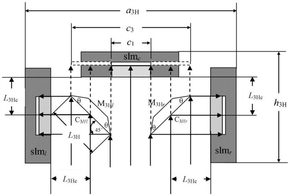
[0066] One 3SLMs array splicing piece is used as the reference display unit, and the other two 3SLMs array splicing pieces are spliced as the left display unit and the right display unit respectively to obtain a 3*3SLMs array splicing piece;
[0067] The 3*3SLMs array splicing piece is used as the reference display unit, and the other two 3*3SLMs array splicing pieces are used as the left display unit and the right display unit respectively, and the light is reflected to the left 3*3SLMs array splicing piece through the left reflection unit and the right reflection unit respectively and the effective display surface of the right 3*3SLMs array splicing piece;
[0068] The mirror image of the effective display surface of the left 3*3SLMs array splicing piece and the...
Embodiment 1
[0081] Embodiment 1, SLMs array splice
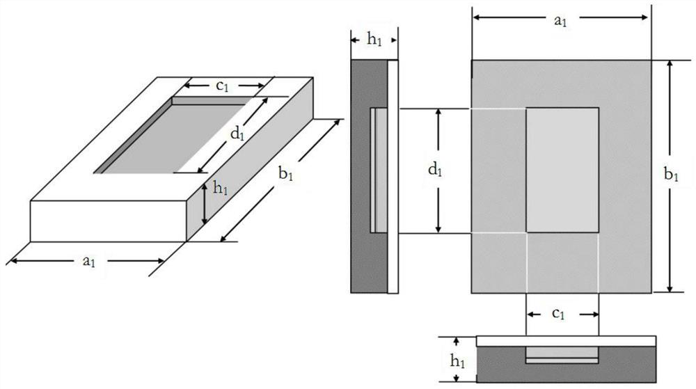
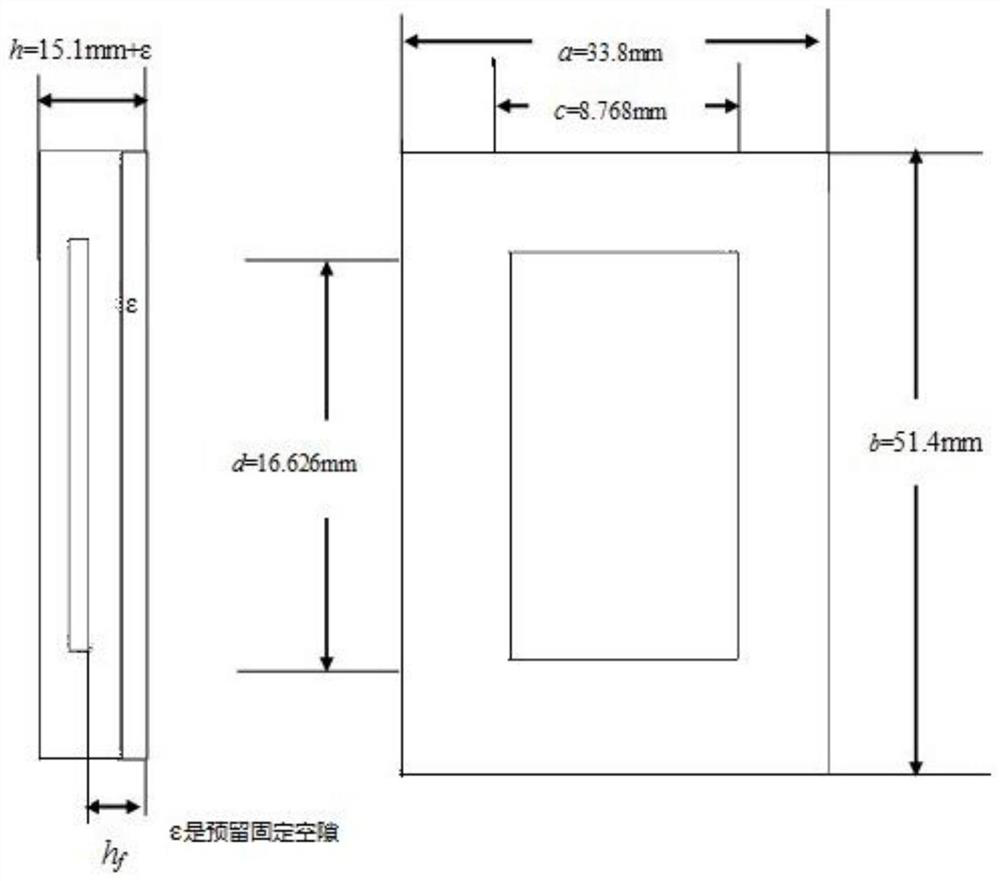
[0082] figure 1 To show the outline structure of the chip, where a 1 is the maximum lateral width (the meaning of "maximum" refers to the measurement of the distance between the outermost edge structures of the shape, the same below); b 1 is the maximum vertical width; h 1 is the maximum thickness; c 1 is the width of the effective display surface; d 1 is the length of the effective display surface. The above five parameters are the basic parameters in the splicing process of the present invention. The basic principle of seamless splicing is to reflect the plane of the effective display area of a display chip to the effective display plane of another display chip through mirror reflection, and connect the edges.
[0083] SLMs array splicing methods include 3 m *3 The splicing of SLMsH array splicing pieces, m is a natural number, which further includes:
[0084] A single SLM display chip is used as a reference display chip uni...
Embodiment 2
[0115] Embodiment 2, a holographic 3D display system based on SLMs array splices
[0116] Figure 13 It is a holographic 3D display system based on SLMs array splicing pieces. The system can be divided into three parts: the illumination optical path ( Figure 14 ), 5*3SLMsH array splices ( Figure 15 ), computational holographic image magnification and viewing angle expansion system ( Figure 16 ).
[0117] The hologram written in the SLMs array splice is read out and diffracted by the parallel light of the illumination light path, and the reconstructed image of the hologram is I hol , I hol The image further enlarged by the lens L is I' hol . The lens L also forms a reduced image I on the effective display plane of the SLMs array splice slms . L Hfun It is a holographic function screen, and its function is to turn the I slms Magnified imaging, its like I' slms Located at the observation plane VP, I' slms is the viewing window for the final 3D image. M3 is a half-...
PUM
 Abstract
Description
Claims
Application Information
 - R&D
- Intellectual Property
- Life Sciences
- Materials
- Tech Scout
- Unparalleled Data Quality
- Higher Quality Content
- 60% Fewer Hallucinations
Browse by: Latest US Patents, China's latest patents, Technical Efficacy Thesaurus, Application Domain, Technology Topic, Popular Technical Reports.
© 2025 PatSnap. All rights reserved.Legal|Privacy policy|Modern Slavery Act Transparency Statement|Sitemap|About US| Contact US: help@patsnap.com


