
Elevator landing door sill device with self-cleaning function

A self-cleaning, sill technology, applied to elevators in buildings, cleaning methods and utensils, removing smoke and dust, etc., can solve the problems of time-consuming, labor-intensive, difficult to remove, and no solution proposed.

Active Publication Date: 2020-05-29
施密特电梯有限公司
View PDF12 Cites 4 Cited by
  • Summary
  • Abstract
  • Description
  • Claims
  • Application Information

AI Technical Summary

Problems solved by technology

[0002] In the sill groove connecting the landing door sill and the landing door, dust and debris tend to accumulate over a long period of time, resulting in the failure of the landing door to close normally. Usually, maintenance personnel are required to periodically clean the dust and foreign objects in the sill groove , time-consuming and labor-intensive, and not easy to be removed
[0003] The utility model patent with the authorized notification number CN208150754U discloses a self-cleaning car sill device for elevators, which blows away the dust and debris in the sill groove by blowing air. The problem with this method is that the cleaning process There is a lot of dust, and the cleaning effect on small stones and other debris is poor
But how to discharge the dust from the ash leakage hole, this patent does not propose a solution

Method used


Image

  • Elevator landing door sill device with self-cleaning function
  • Elevator landing door sill device with self-cleaning function
  • Elevator landing door sill device with self-cleaning function

Examples


Embodiment Construction

[0034] Embodiments of the technical solutions of the present invention will be described in detail below in conjunction with the accompanying drawings. The following examples are only used to illustrate the technical solutions of the present invention more clearly, and therefore are only examples, rather than limiting the protection scope of the present invention.

[0035] It should be noted that, unless otherwise specified, the technical terms or scientific terms used in this application shall have the usual meanings understood by those skilled in the art to which the present invention belongs.

[0036] In the description of the present application, it should be understood that the terms "center", "longitudinal", "transverse", "length", "width", "thickness", "upper", "lower", "front", " Back", "Left", "Right", "Vertical", "Horizontal", "Top", "Bottom", "Inner", "Outer", "Clockwise", "Counterclockwise", "Axial", The orientation or positional relationship indicated by "radial"...


PUM


Abstract

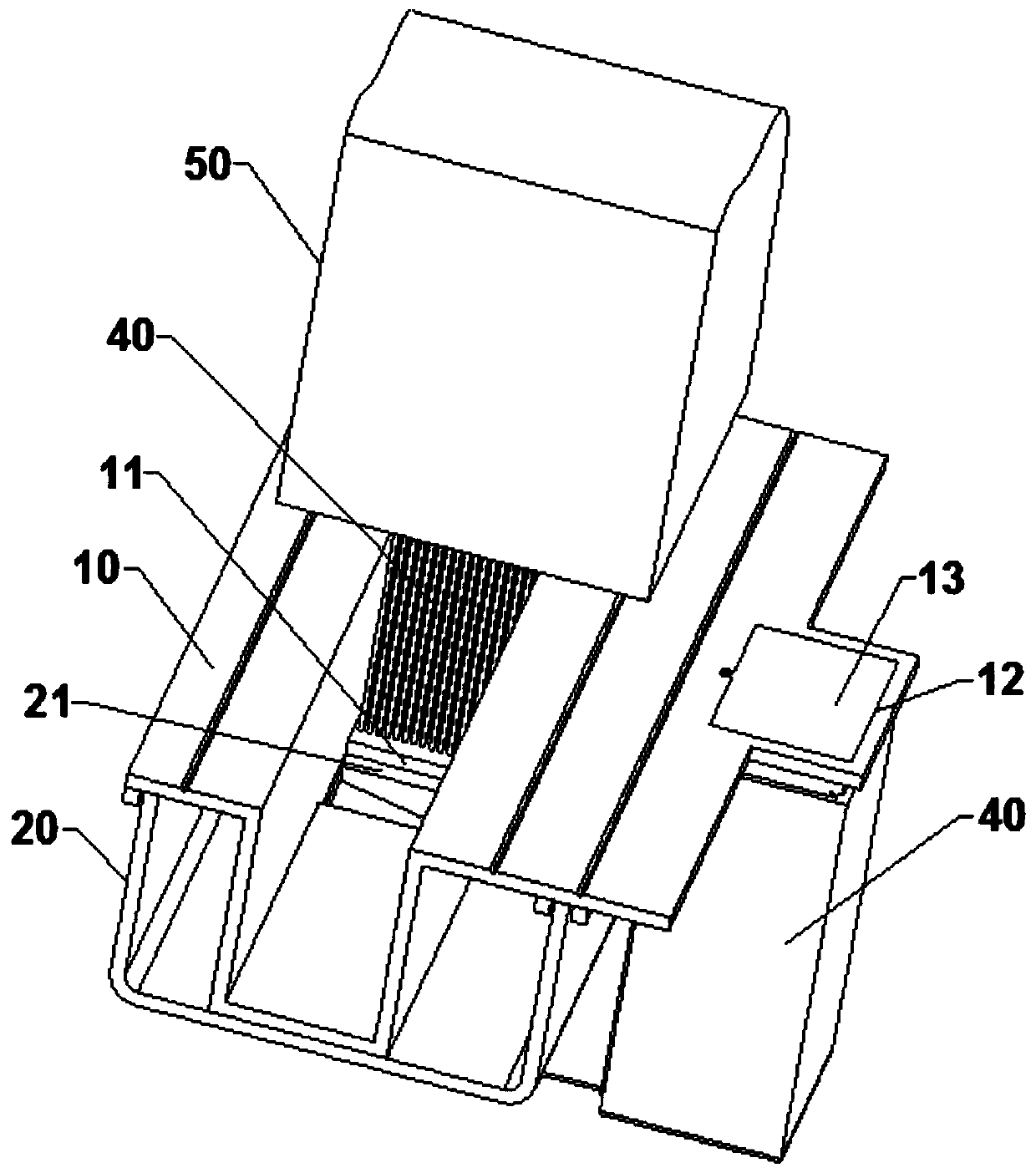
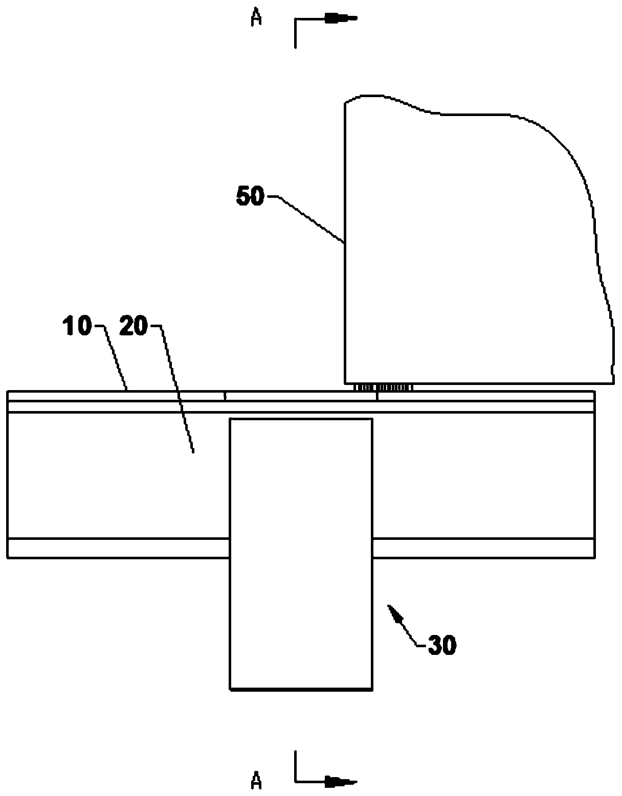
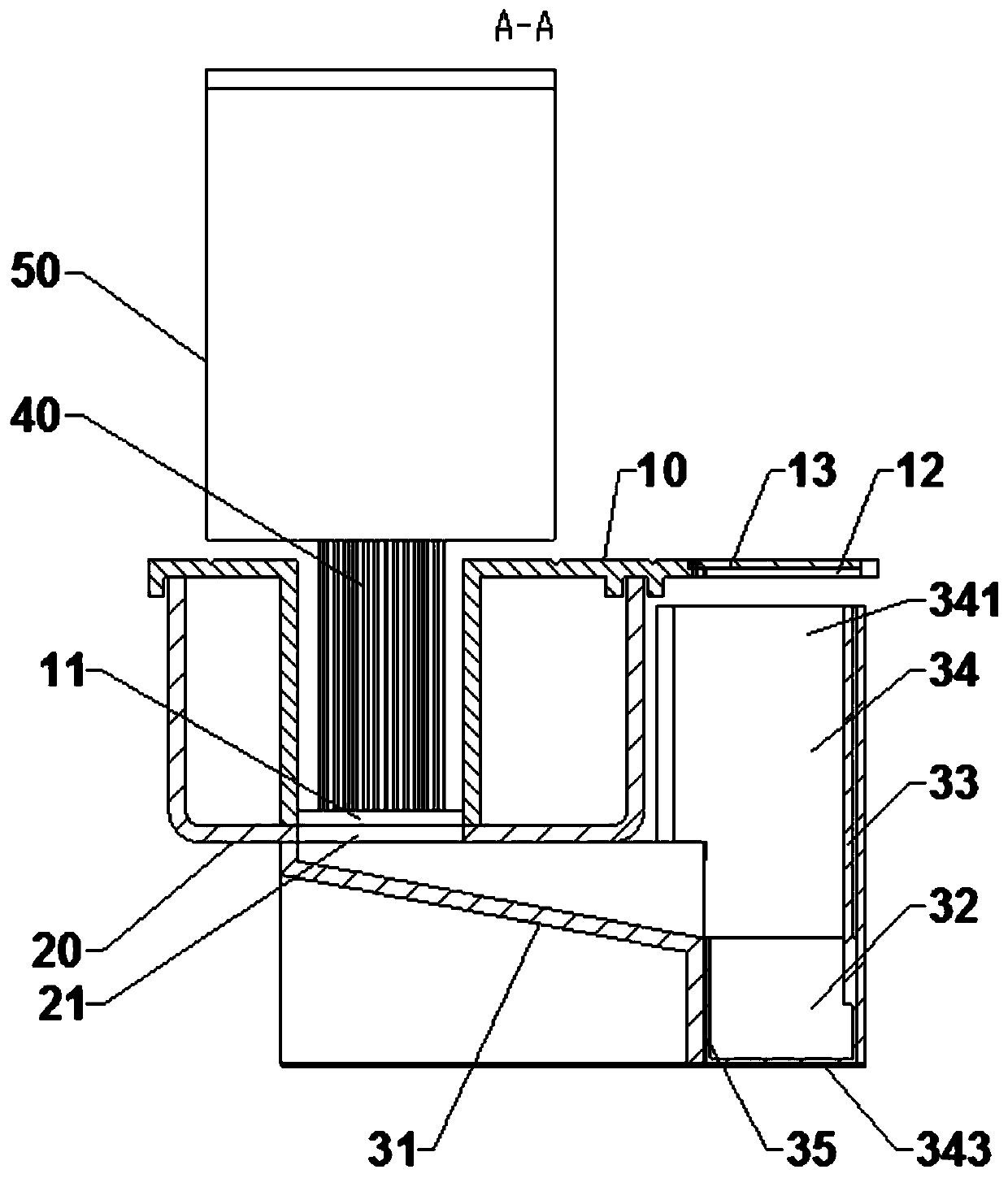
The invention belongs to elevator components, and provides an elevator landing door sill device with a self-cleaning function. The elevator landing door sill device comprises a landing door sill and asill bracket; the landing door sill is provided with a sill groove, a hairbrush fixedly connected with a landing door is arranged in the sill groove, and a first ash leakage hole and a second ash leakage hole which are in communication with each other are correspondingly formed in the middle parts of the landing door sill and the sill bracket; the elevator landing door sill device further a dustcollecting device, a collecting box and a handle, wherein the dust collecting device comprises an ash discharging groove fixedly formed in the bottom of the sill bracket, the ash discharging groove isprovided with a feeding end and a discharging end, and the feeding end is located under the second ash leaking hole and is higher than the discharging end; the collecting box can move in the longitudinal direction and can move to the discharging end of the ash discharging groove so as to be used for collecting dust discharged from the ash discharging groove; the lower end of the handle is fixedlyconnected with the collecting box; and an ash taking opening allowing the collecting box and the handle to pass through is formed in the upper surface of the landing door sill, and a cover plate capable of being opened and closed is arranged at the ash taking opening. According to the elevator landing door sill device, the function that maintenance personnel regularly take away dust discharged from the dust leaking holes is achieved.

Description

technical field [0001] The invention belongs to elevator components, in particular to an elevator floor door sill device with self-cleaning function. Background technique [0002] In the sill groove connecting the landing door sill and the landing door, dust and debris tend to accumulate over a long period of time, resulting in the failure of the landing door to close normally. Usually, maintenance personnel are required to periodically clean the dust and foreign objects in the sill groove , time-consuming and laborious, and not easy to be removed. [0003] The utility model patent with the authorized notification number CN208150754U discloses a self-cleaning car sill device for elevators, which blows away the dust and debris in the sill groove by blowing air. The problem with this method is that the cleaning process There is a lot of dust, and the cleaning effect on small stones and other debris is poor. [0004] The utility model patent whose authorized notification numb...

Claims


Application Information

Patent Timeline
IPC IPC(8): B66B13/30B08B13/00B08B15/00
CPCB66B13/301B08B13/00B08B15/00
Inventor 彭晖李生惠邓国浪
Owner 施密特电梯有限公司
Features
  • Generate Ideas
  • Intellectual Property
  • Life Sciences
  • Materials
  • Tech Scout
  • Unparalleled Data Quality
  • Higher Quality Content
  • 60% Fewer Hallucinations
Learn More