
Conical pendulum mechanism and roof fan

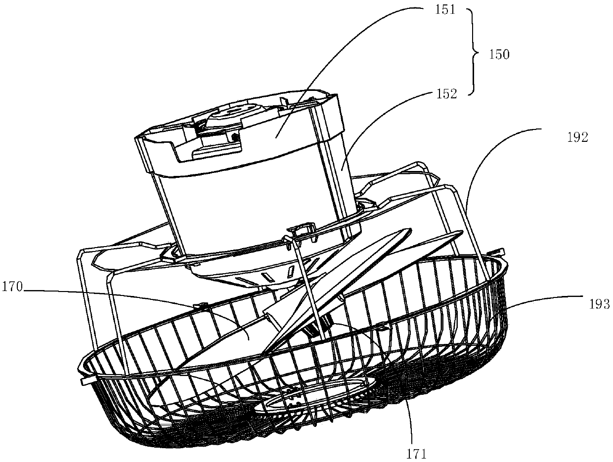
A technology of cone pendulum and rotating shaft, which is applied in the field of cone pendulum mechanism and roof fan, which can solve the problem of small air supply area of ​​roof fan, and achieve the effect of expanding the rotation range and air supply range

Inactive Publication Date: 2020-06-02
GD MIDEA ENVIRONMENT APPLIANCES MFG +1
View PDF5 Cites 2 Cited by
  • Summary
  • Abstract
  • Description
  • Claims
  • Application Information

AI Technical Summary

Problems solved by technology

[0003] The main purpose of the present invention is to provide a cone pendulum mechanism, which aims to solve the problem of the small air supply area of ​​the roof fan in the prior art

Method used


Image

  • Conical pendulum mechanism and roof fan
  • Conical pendulum mechanism and roof fan
  • Conical pendulum mechanism and roof fan

Examples


Embodiment Construction

[0030] The following will clearly and completely describe the technical solutions in the embodiments of the present invention with reference to the accompanying drawings in the embodiments of the present invention. Obviously, the described embodiments are only part of the embodiments of the present invention, not all of them. Based on the embodiments of the present invention, all other embodiments obtained by persons of ordinary skill in the art without creative efforts fall within the protection scope of the present invention.

[0031] It should be noted that all directional indications (such as up, down, left, right, front, back...) in the embodiments of the present invention are only used to explain the relationship between the components in a certain posture (as shown in the accompanying drawings). Relative positional relationship, movement conditions, etc., if the specific posture changes, the directional indication will also change accordingly.

[0032] In addition, the ...


PUM


Abstract

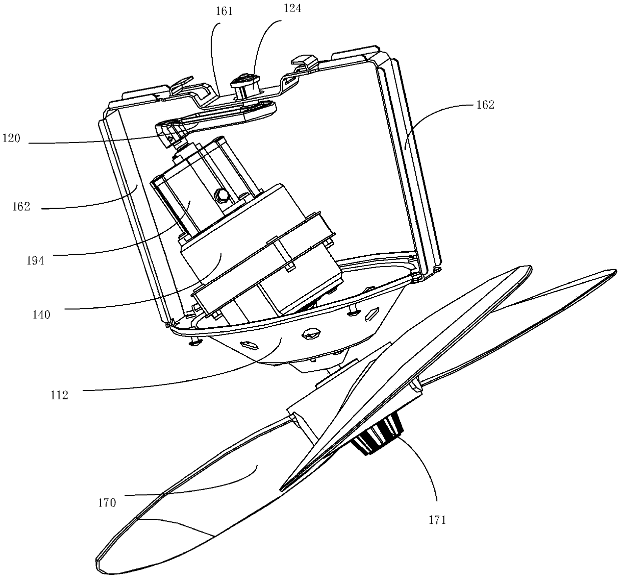
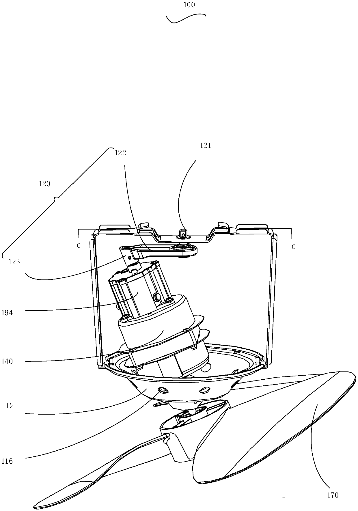
The invention provides a conical pendulum mechanism and a roof fan provided with the conical pendulum mechanism. The conical pendulum mechanism comprises a support, a rotating shaft, a universal ballbearing, a connecting rod and a motor, wherein the universal ball bearing is arranged on the support, one end of the connecting rod is rotationally connected to the rotating shaft, the other end of the connecting rod is rotationally connected with the end, close to the rotating shaft, of an output shaft of the motor, the connecting rod is driven by the motor to conduct conical rotation around therotating shaft, the end, far away from the rotating shaft, of the output shaft of the motor penetrates through a universal ball of the universal ball bearing and is exposed outside the universal ballbearing, the rotating shaft is fixed to the position, avoiding the universal ball bearing, of the support, the support is used for fixing the conical pendulum mechanism to an external fixed object, orthe rotating shaft is used for being directly fixed to the external fixed object. According to the mechanism, the universal ball bearing is arranged on the support, so that the conical pendulum motion of the whole conical pendulum mechanism is realized, when the conical pendulum mechanism is used for an oscillating mechanism of the roof fan, the air supply range of the roof fan can be further expanded, and various requirements of users are met.

Description

technical field [0001] The invention relates to the field of mechanical structures, in particular to a cone pendulum mechanism and a roof fan with the cone pendulum mechanism. Background technique [0002] In the prior art, the centers of several fan blades of the roof fan are suspended and connected to a motor fixed on the ceiling, and the rotation of the motor drives the rotation of the fan blades. The roof fan made in this way can only feel the air supply from the roof fan in a fixed area, that is, the area directly below the motor, but not in other areas, and the scope of use is limited. Contents of the invention [0003] The main purpose of the present invention is to provide a cone pendulum mechanism, aiming to solve the problem in the prior art that the range of the air supply area of ​​the roof fan is small. [0004] In order to achieve the above object, the present invention proposes a cone pendulum mechanism, comprising: a bracket, a rotating shaft, a universal ...

Claims


Application Information

Patent Timeline
Patent Type & Authority Applications(China)
IPC IPC(8): F04D25/10F04D29/056
CPCF04D25/105F04D29/056
Inventor 张焕明
Owner GD MIDEA ENVIRONMENT APPLIANCES MFG
Learn More