D-shaped temporary beam erecting method for underneath pass railway frame bridge type tunnel

A frame bridge and convenient beam technology, applied in the field of road and bridge engineering, can solve problems such as the inability to meet the support piles of D-type convenient beams.

Inactive Publication Date: 2020-06-05
CHINA RAILWAY ERYUAN ENG GRP CO LTD
View PDF4 Cites 8 Cited by
  • Summary
  • Abstract
  • Description
  • Claims
  • Application Information

AI Technical Summary

Problems solved by technology

[0004] The purpose of the present invention is to provide a bridge tunnel that passes under a railway frame bridge in view of the problem in the prior art that the extreme depth of excavation piles cannot meet the requirements of D-shaped beam support piles under special geological conditions. D-shaped beam overhead method

Method used


Image

  • D-shaped temporary beam erecting method for underneath pass railway frame bridge type tunnel
  • D-shaped temporary beam erecting method for underneath pass railway frame bridge type tunnel
  • D-shaped temporary beam erecting method for underneath pass railway frame bridge type tunnel

Examples


Embodiment 1

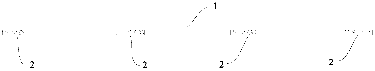
[0038] A D-shaped convenience beam overhead method passing under a railway frame bridge tunnel, comprising the following steps:

[0039] Step 1: If figure 1 As shown, utilize skylight time, on existing railway embankment (below track surface 1), construct open-cut foundation 2, as the fulcrum of temporary beam 3, wherein said open-cut foundation 2 is strip foundation;

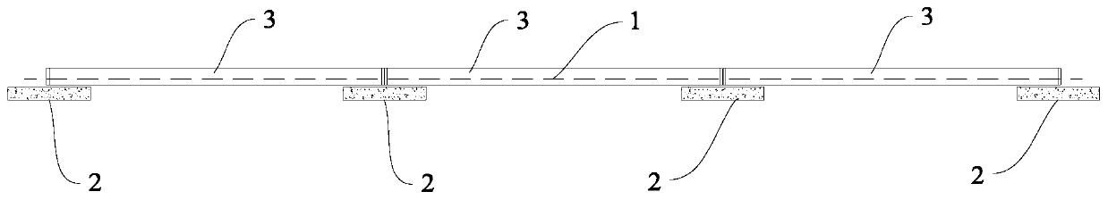
[0040] Step 2: If figure 2 As shown, using the skylight time, a temporary beam 3 is erected on the open excavation foundation 2 to reinforce the line, wherein the temporary beam 3 is a D-shaped beam or a rail beam;

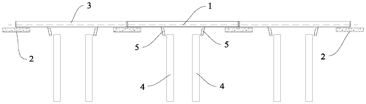
[0041] Step 3: If image 3 As shown, the excavated pile 4 is excavated on the roadbed after reinforcement, and the pile 4 is dug to 10m-15m below the road shoulder, and the pile 4 is poured, and a retaining pile is set at the end of the pile 4 Ballast Wall 5:

[0042] Step 4: If Figure 4 As shown, after the hole-digging piles 4 reach the design strength, the reinforced concrete lateral suppo...


PUM


Abstract

The invention discloses a D-shaped temporary beam overhead method for an underneath passing a railway frame bridge tunnel, which comprises the following steps of: constructing an open cut foundation on an existing railroad bed by using skylight time; erecting a temporary auxiliary beam reinforcing line on the open cut foundation; digging hole digging piles on the reinforced roadbed, digging the hole digging piles to 15 m below a road shoulder, and pouring the hole digging piles; after the hole digging piles reach the designed strength, constructing transverse supports between the two rows of hole digging piles, excavating a soil layer between the two rows of hole digging piles in a layered mode, forming a drilled pile construction foundation pit, and the transverse supports are constructedat the bottom of the drilled pile construction foundation pit; the drilled pile construction foundation pit is used as a construction platform, constructing drilled piles, after drilled pile construction is completed, backfilling the drilled pile construction foundation pit, and dismantling the temporary auxiliary beams; the drilled piles serve as D-shaped auxiliary beam supporting piles, erecting a D-shaped auxiliary beam, and constructing transverse supports between the drilled piles; excavating a frame foundation pit below the D-shaped auxiliary beams, and constructing a frame bridge typetunnel; and backfilling the frame foundation pit, removing the D-shaped auxiliary beam, and recovering the line.

Description

technical field [0001] The invention relates to the technical field of road and bridge engineering, in particular to an overhead method of a D-shaped convenient beam passing under a railway frame bridge tunnel. Background technique [0002] At present, the construction of underground tunnels under large railway yards generally adopts D-shaped convenient beams to overhead the existing railway construction, and excavates excavated piles on the reinforced roadbed as D-shaped convenient beam buttresses for the construction of the existing offline frame. This construction method can meet the construction needs of most frame tunnels passing through existing railways. [0003] However, in areas with poor geology (no bedrock) and high groundwater levels, such as lake sedimentary areas, coastal areas, etc., although the digging piles have reached the limit digging depth (up to 15 meters), the limit digging depth of the digging piles Still can not be used as the area of ​​D-type conv...

Claims


Application Information

Patent Timeline
Patent Type & Authority Applications(China)
IPC IPC(8): E01D18/00E01D21/00E02D5/34E02D17/02
CPCE01D18/00E01D21/00E02D5/34E02D17/02
Inventor 陈洪春徐建华罗星文许志艳刘发明
Owner CHINA RAILWAY ERYUAN ENG GRP CO LTD
Why Eureka
Try Eureka