Laser ranging device

A laser ranging and laser technology, applied in the field of rangefinders, can solve the problem of inability to solve the aiming problem, increase the difficulty and capture time of capturing the correct distance, and cannot accurately lock the aiming target, etc., so as to solve the problem of long capture time and improve capture. Speed, difficult to solve effects

Pending Publication Date: 2020-06-05
LANHAI PHOTOELECTRICITY TECH CO LTD
View PDF3 Cites 1 Cited by
  • Summary
  • Abstract
  • Description
  • Claims
  • Application Information

AI Technical Summary

Problems solved by technology

When the user is using it, due to the handheld mode, the user cannot precisely lock the aiming target and ensure that the laser beam is pointed at the correct object
[0004] In addition, some rangefinders are available with advanced features such as ARC (Angular Range Compensation) and multi-range capability that can display the distance to the closest target among multiple objects so that it is easy to measure the distance to the flagpole instead of the background object, it still cannot solve the aiming problem, which increases the difficulty and capture time for the user to capture the correct distance

Method used


Image

  • Laser ranging device
  • Laser ranging device
  • Laser ranging device

Examples


Embodiment 1

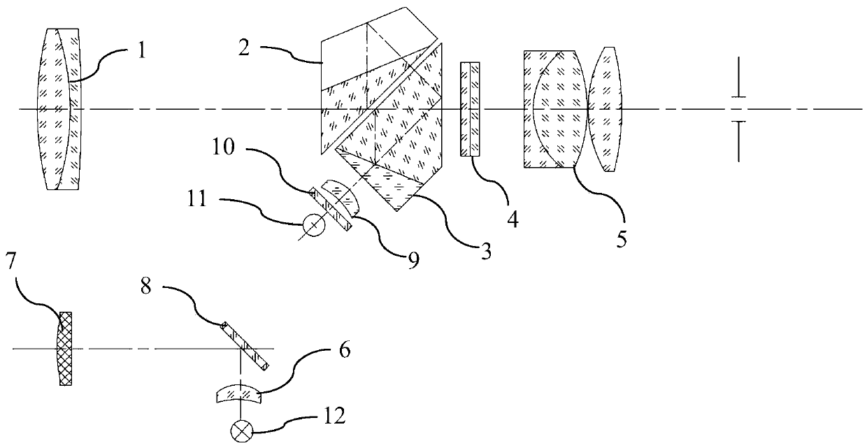
[0033] Please refer to the attached figure 1 , the present invention provides a laser distance measuring device, comprising: a monocular telescope, a laser emitting system, a laser receiving system and a scanner 8, wherein the laser emitting system emits laser light which is reflected by the scanner 8 and hits the measured target, The laser light reflected by the measured target is received by the laser receiving system; the monocular telescope is used for framing the measured target.

[0034] In order to further optimize the above-mentioned technical scheme, such as Figure 7 As shown, the scanner 8 can rotate and scan around the center of the viewfinder to change the emitting direction of the laser, and the laser scanning covers the scanning frame area of ​​the viewfinder. Figure 7 In (a), the angle between the scanner 8 and the laser incident direction is 45°, Figure 7 In (b), the angle between the scanner 8 and the laser incident direction is 48.5°, Figure 7 In (c), ...

Embodiment 2

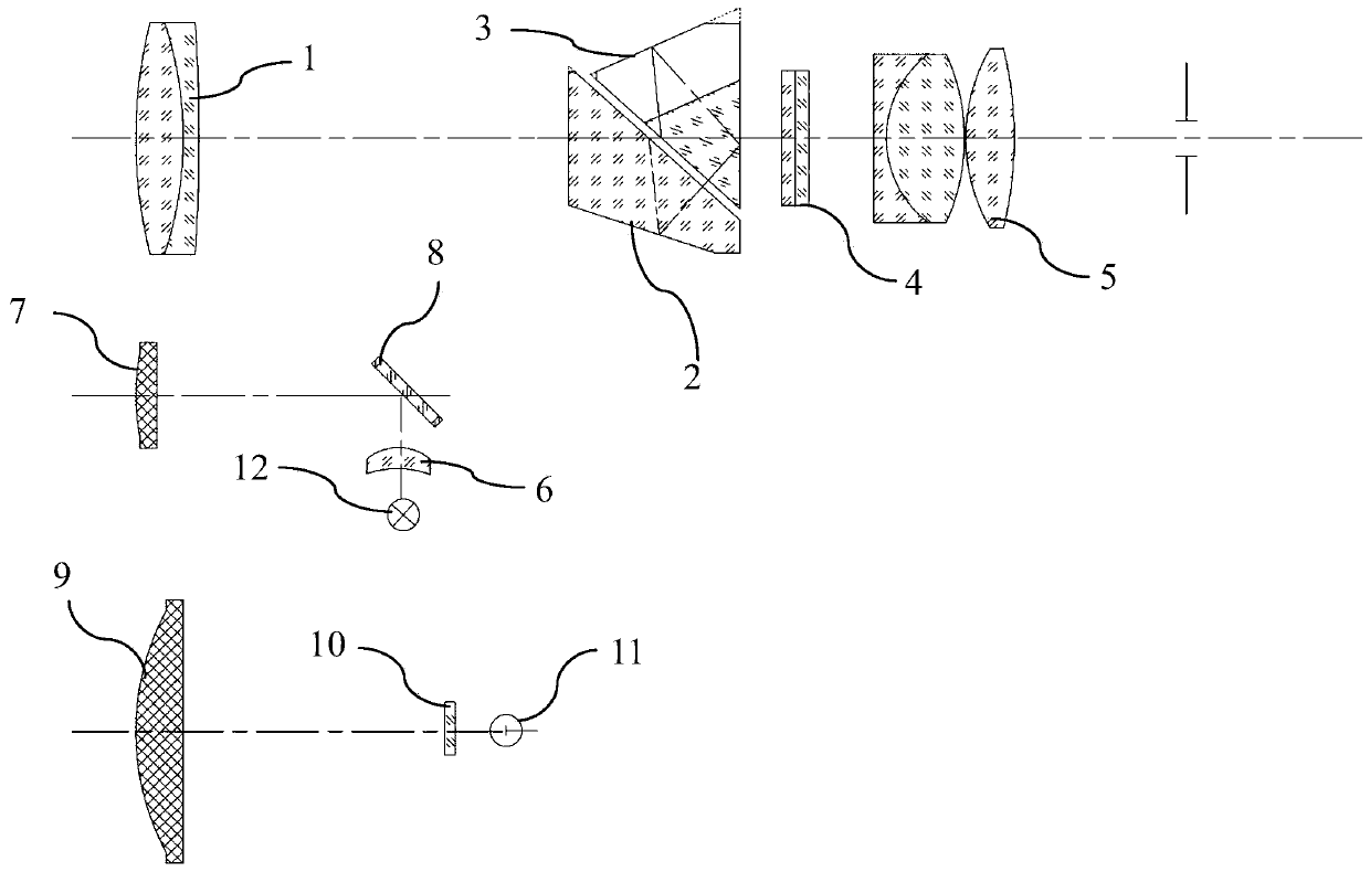
[0045] Reference attached figure 2 The difference between this embodiment and Embodiment 1 is that the positions of the laser emitting system and the laser receiving system are different. In this embodiment, the semiconductor laser emitter 12 emits laser light, which is transmitted through the first transmitting lens 6, reflected by the scanner 8, transmitted through the second transmitting lens 7, and then emitted. After reaching the measured target, the optical signal is reflected, and the reflected optical signal passes through the receiving lens 9 in turn. , After the optical filter 10, it is received by the photoelectric receiving tube 11.

Embodiment 3

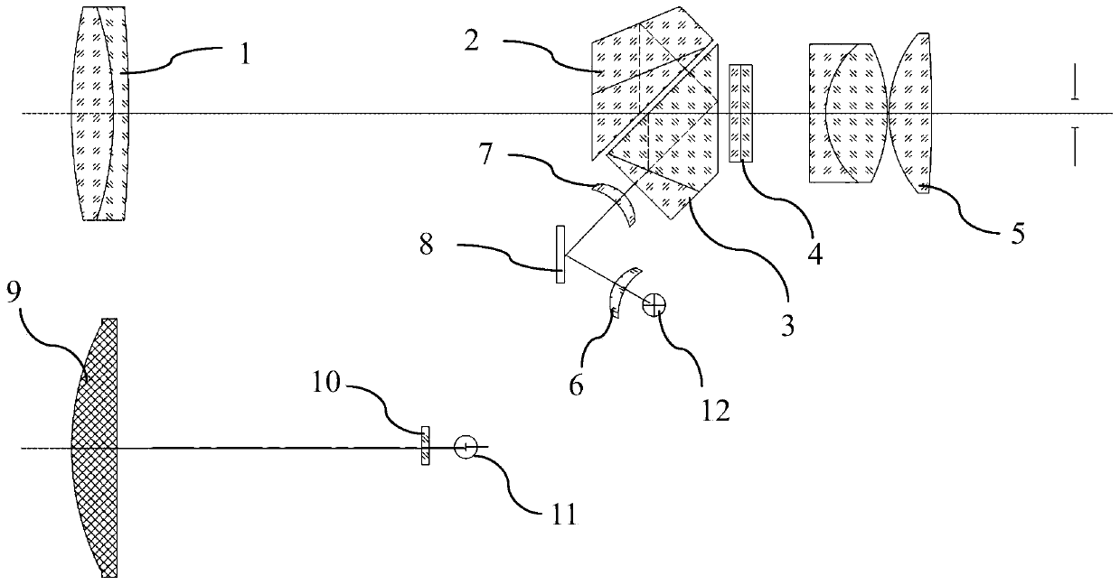
[0047] Reference attached image 3 The difference between this embodiment and Embodiment 1 is that the positions of the laser emitting system and the laser receiving system are different. In the present embodiment, semiconductor laser emitter 12 sends laser light, after transmitting lens 1 6 transmission, scanner 8 reflection, transmitting lens 2 7 transmissions, then successively through glued prism 3, roof half pentaprism 2, exit after objective lens 1, arrive at The light signal is reflected by the measured object, and the reflected light signal is received by the photoelectric receiving tube 11 after passing through the receiving lens 9 and the optical filter 10 in sequence.


PUM


Abstract

The invention discloses a laser ranging device, and the device comprises a monocular telescope, a laser emitting system, a laser receiving system and a scanner; the laser emitted by the laser emittingsystem is reflected by the scanner and then is emitted to a measured target, and the laser reflected by the measured target is received by the laser receiving system; the monocular telescope is usedfor framing of a measured target. According to the invention, region scanning can be carried out on a measured target, the aiming difficulty is greatly reduced, and the capturing speed is improved.

Description

technical field [0001] The invention belongs to the technical field of distance measuring instruments, and more specifically relates to a laser distance measuring device. Background technique [0002] Laser rangefinders are popular with golfers, hunters and outdoorsmen because of their ranging and observation performances. Laser rangefinders have been widely used in golf courses to measure target distances, especially the distance to holes. [0003] Laser rangefinders do not rely on GPS coordinates, but their accuracy is susceptible to the user operating the device. Typically, the user points the laser rangefinder at the object through the center of the viewfinder. Once the object is in the center, the user activates the laser beam, which is fired by the device towards the target object. The laser beam is reflected by the object, and part of it returns to the device, and the device calculates and displays the distance of the target object based on, for example, the time di...

Claims


Application Information

Patent Timeline
Patent Type & Authority Applications(China)
IPC IPC(8): G01S17/08G01S7/481
CPCG01S17/08G01S7/4817
Inventor 刘崇求范益群
Owner LANHAI PHOTOELECTRICITY TECH CO LTD
Why Eureka
Try Eureka