A method of installing a self-locking joint

An installation method and self-locking technology, which is applied in the assembly/disassembly of contact pieces, parts of connection devices, connections, etc., can solve problems such as poor sealing, and achieve the effect of good toughness, high strength, and not easy to damage

Active Publication Date: 2021-06-11
珠海福睿电子科技有限公司
View PDF0 Cites 0 Cited by
  • Summary
  • Abstract
  • Description
  • Claims
  • Application Information

AI Technical Summary

Problems solved by technology

For this reason, the present invention proposes a method for installing a self-locking joint, which can solve the problem of poor sealing performance after the joint is installed

Method used


Image

  • A method of installing a self-locking joint
  • A method of installing a self-locking joint
  • A method of installing a self-locking joint

Examples


Embodiment Construction

[0031] Embodiments of the present invention are described in detail below, and examples of the embodiments are shown in the drawings, wherein the same or similar reference numerals denote the same or similar elements or elements having the same or similar functions throughout. The embodiments described below by referring to the figures are exemplary only for explaining the present invention and should not be construed as limiting the present invention.

[0032] In the description of the present invention, it should be understood that the orientation descriptions, such as up, down, front, back, left, right, etc. indicated orientations or positional relationships are based on the orientations or positional relationships shown in the drawings, and are only In order to facilitate the description of the present invention and simplify the description, it does not indicate or imply that the device or element referred to must have a specific orientation, be constructed and operated in ...


PUM


Abstract

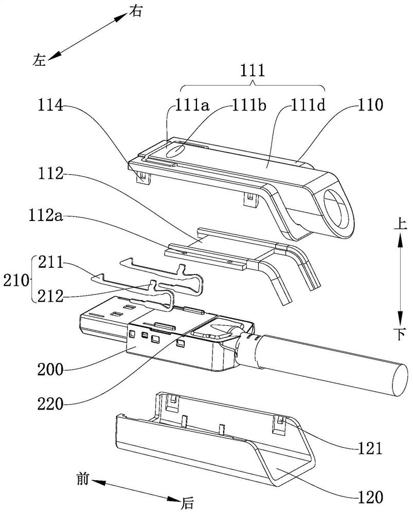
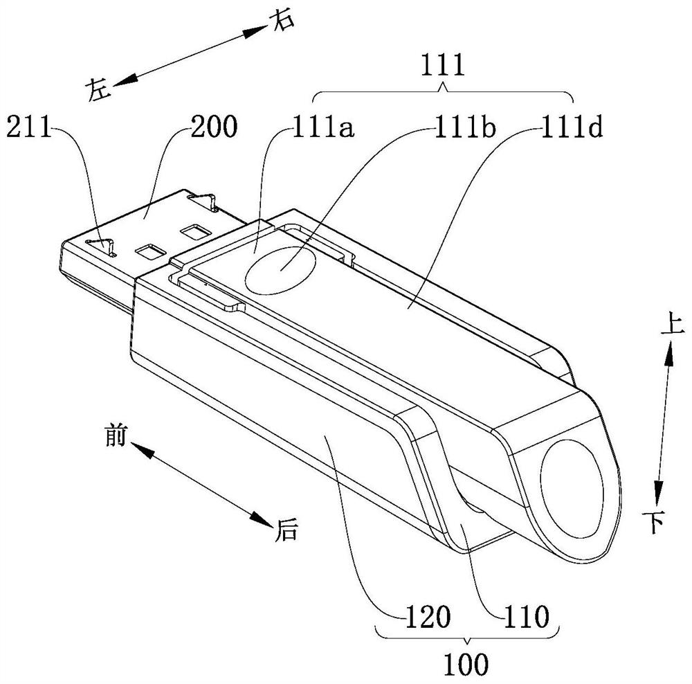
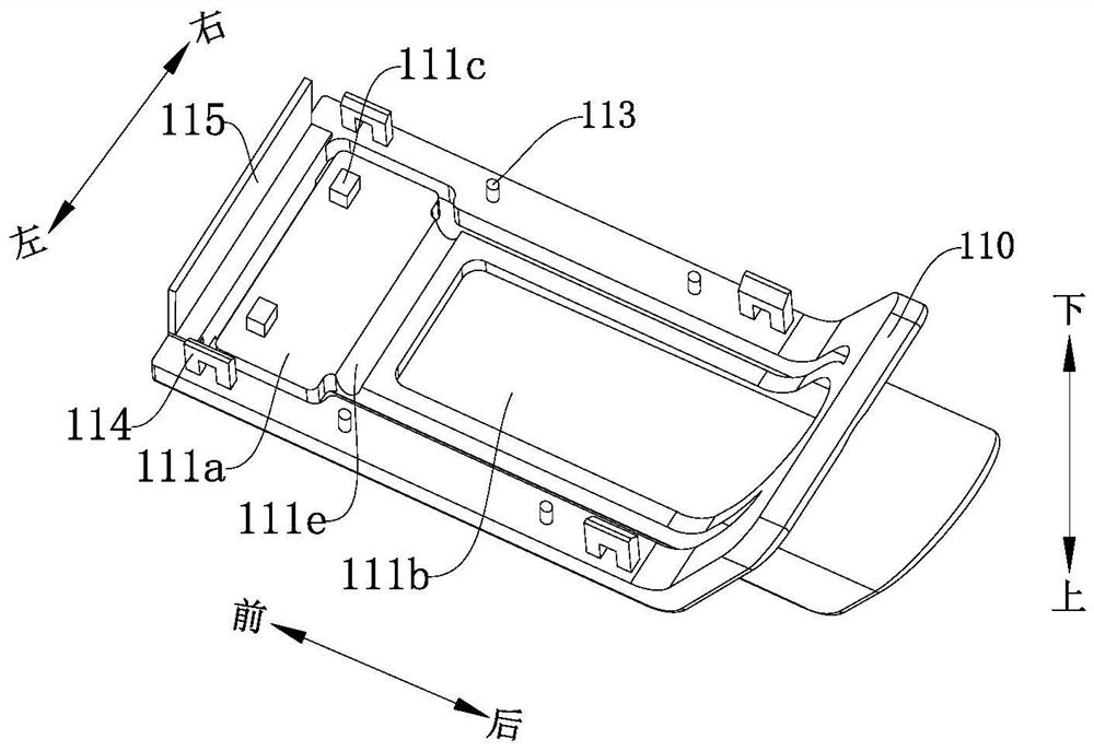
The invention discloses a method for installing a self-locking joint. The self-locking joint comprises: an upper shell, a lower shell, a joint body and a blocking piece. The upper end of the joint body is provided with an elastic clip, and the upper shell is provided with a pressing part and a wire. There is a gap between the upper shell and the pressing part, and the installation steps of the self-locking joint are as follows: Step a: Connect the cable at the rear end of the joint body; Step b: Apply downward pressure on the joint body to lock the joint The body is pressed into the lower case; step c: install the baffle to the lower end of the upper case; step d: pass the cable through the cable hole, and move the upper case to the top of the lower case along the cable; step e: apply force to the upper case and / or the lower case to drive them closer to each other, fasten the upper case and the lower case, install the stopper in the upper case, use the stopper The sheet is used to cover the gap on the upper shell to achieve the purpose of sealing the self-locking joint.

Description

technical field [0001] The invention relates to the technical field of joint installation methods, in particular to a self-locking joint installation method. Background technique [0002] Connectors are often used to connect cables and devices. In order to prevent the connectors from being easily separated from the device, the connectors generally have a self-locking function. [0003] There are generally two types of self-locking joints in the past. One is that both the upper and lower housings are provided with grooves for placing cables. The groove protrudes, and the installation method is to first place the connector and the cable in the upper shell or the lower shell, and then directly buckle the upper shell and the lower shell. The second is to set a cable through hole in the upper shell or the lower shell, first insert the cable into the cable through hole, then move the upper shell or the lower shell to the joint position along the cable, and then insert the corresp...

Claims


Application Information

Patent Timeline
Patent Type & Authority Patents(China)
IPC IPC(8): H01R43/00H01R43/20H01R13/52
CPCH01R13/52H01R13/5213H01R43/005H01R43/20
Inventor 张伟权韦子欧
Owner 珠海福睿电子科技有限公司
Why Eureka
Try Eureka