Full-automatic intelligent holding pole for communication tower antenna

An iron tower antenna and fully automatic technology, applied in the field of communication signal transmission, can solve the problems of staff inconvenience, manual changes, and increase the workload of staff

Pending Publication Date: 2020-06-09
甘肃铧城工贸有限公司
View PDF0 Cites 2 Cited by
  • Summary
  • Abstract
  • Description
  • Claims
  • Application Information

AI Technical Summary

Problems solved by technology

[0004] In order to solve the original automatic intelligent pole holding pole of the communication tower proposed in the above-mentioned background technology, the signal emission angle cannot be changed or needs to be manually changed by the staff, which increases the work burden of the staff and brings inconvenience to the staff, and the existing principle Some communication towers have automatic smart poles that cannot be adjusted in all aspects, which brings inconvenience to the staff

Method used


Image

  • Full-automatic intelligent holding pole for communication tower antenna
  • Full-automatic intelligent holding pole for communication tower antenna
  • Full-automatic intelligent holding pole for communication tower antenna

Examples


Embodiment 1

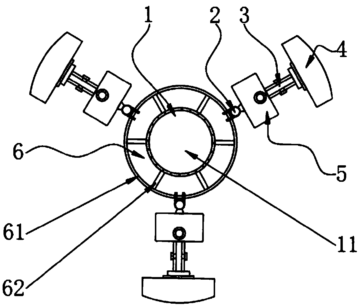
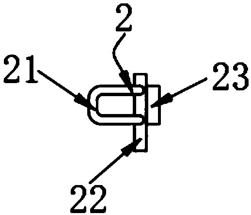
[0036] see Figure 1-Figure 3 , the present invention provides a technical solution: a fully automatic intelligent pole holding pole for a communication tower antenna, including a support assembly 1, a fixing assembly 6 located on one side of the support assembly 1, and a connecting assembly 2 sleeved on the fixing assembly 6, and the support assembly 1 includes a support rod 11, the fixing assembly 6 includes a steel ring 61 and an inner connecting rod 62, the steel ring 61 is sleeved on one end of the supporting rod 11, and the inner side wall of the fixing assembly 6 is welded and fixed with an inner connecting rod 62, the fixing assembly 6 and The support rod 11 is fixed by welding the inner connecting rod 62. The connecting assembly 2 is mainly composed of a connecting ring 21, a first connecting plate 22 and a clamping plate 23. The connecting ring 21 is sleeved on the outer wall of the steel ring 61, and the steel ring 61 is engaged Connection, the side of the connectin...

Embodiment 2

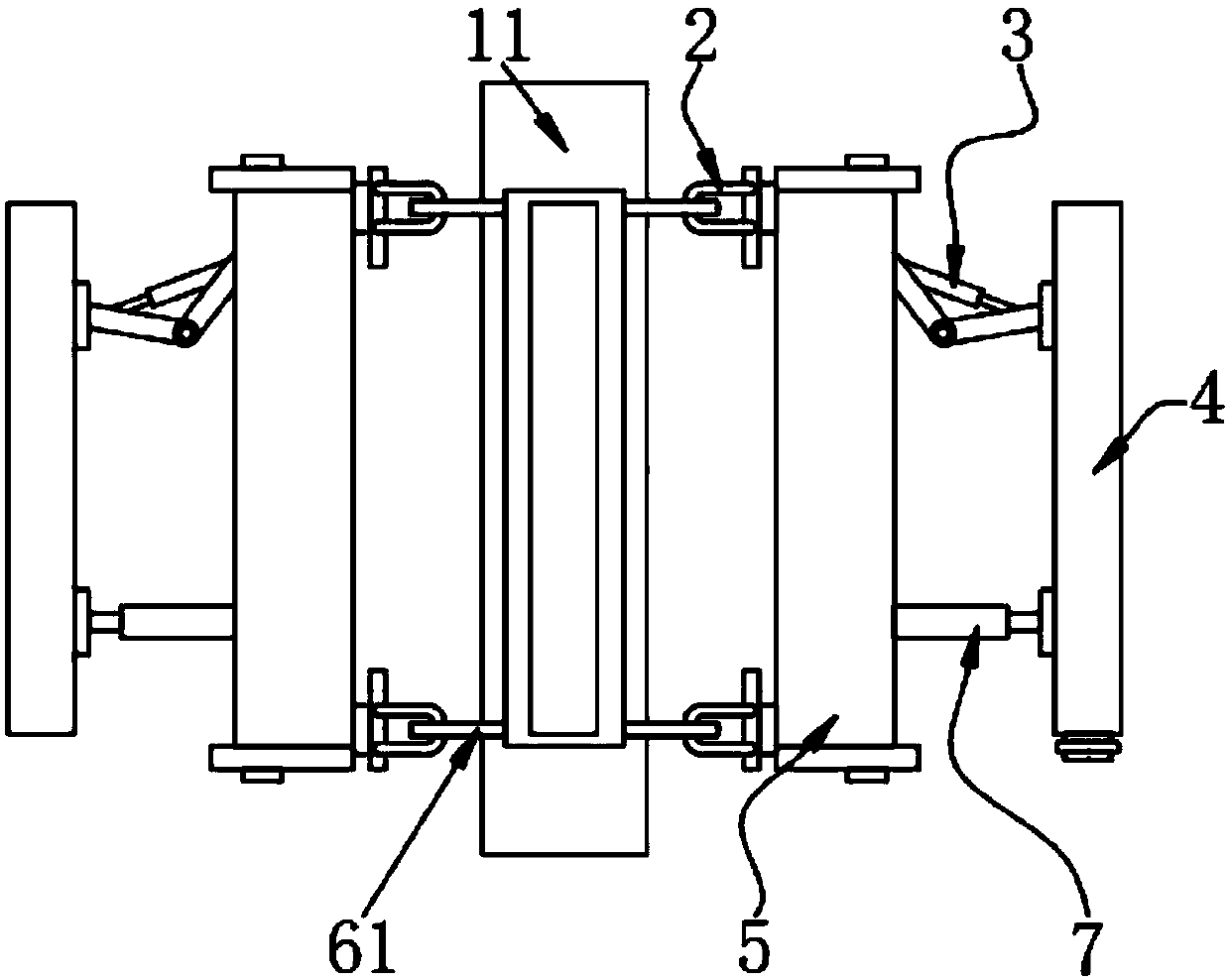
[0044] see Figure 4 , in this embodiment: the vertical movement of the signal transmitting assembly 4 is introduced, and the placement assembly 5 includes a holding rod 51, a first motor 52, a first screw 53, a second screw 54, a third screw 55 and a second screw The motor 56, the holding rod 51 is located on the side of the clamping plate 23 away from the first connecting plate 22, the holding rod 51 and the clamping plate 23 are welded and fixed, and the inside of the holding rod 51 is a hollow structure, the first motor 52 is located inside the holding rod 51, and The outer surface of the first motor 52 is welded and fixed with a first base 521, the first motor 52 and the holding rod 51 are welded and fixed by the first base 521, and the transmission end of the first motor 52 is fixedly connected with a first screw rod 53, One end of the first screw mandrel 53 is connected to the transmission end of the first motor 52, and the other end extends to the top of the first moto...

Embodiment 3

[0050] see Figure 5 , in the present embodiment: the horizontal rotation of the signal transmitting assembly 4 is introduced, (combined with the conditions of embodiment 2) a second motor 56 is provided on one side of the second screw mandrel 54, and the outer wall of the second motor 56 is fixedly provided with a second The base 561, the second motor 56 and the holding rod 51 are welded and fixed by the second base 561, the transmission end of the second motor 56 is provided with a transmission chain 563, and the outer wall of the third screw rod 55 is close to the first sleeve shaft 553 The top of the transmission gear 562 is also sleeved, and one end of the transmission chain 563 is sleeved on the transmission gear 562, and the transmission gear 562 is slidingly connected, and the other end of the transmission chain 563 is sleeved on the transmission end of the second motor 56.

[0051] In this embodiment: when the second motor 56 rotates, the transmission chain 563 drives...


PUM


Abstract

The invention belongs to the technical field of communication signal transmission and particularly relates to a full-automatic intelligent holding pole for the communication tower antenna. The full-automatic intelligent holding pole for the communication tower antenna comprises a supporting assembly, a fixing assembly located on one side of the supporting assembly, and a connecting assembly arranged on the fixing assembly in a sleeving mode, wherein the supporting assembly comprises a supporting rod, the fixing assembly comprises a steel ring and an inner connecting rod, the steel ring is arranged at one end of the supporting rod in a sleeving mode, the inner connecting rod is welded and fixed to the inner side wall of the fixing assembly, and the fixing assembly and the supporting rod arewelded and fixed through the inner connecting rod; the third screw rod longitudinally penetrates through the holding pole; a bearing is arranged at one end exposed out of the holding pole; the thirdscrew rod is rotationally connected with the holding pole through a bearing; and when the transmission teeth rotate, a second connecting shaft and a third connecting shaft are the same in structure, so that the second connecting shaft and the third connecting shaft rotate along the threads on the first screw rod and the second screw rod, the third screw rod further rotates in the holding rod through the bearing, and horizontal rotation of the signal transmitting assembly is further realized.

Description

technical field [0001] The invention belongs to the technical field of communication signal transmission, and in particular relates to a fully automatic intelligent pole holding pole for a communication iron tower antenna. Background technique [0002] After decades of development in China, the communication towers have been developed in China. Whether it is a single-tube tower, an angle steel tower, a three-tube tower, a roof bracket or a special shape tower, the suspension method of the antenna is traditionally bolted and fixed on the tower 70MM-75MM× The 4MM pipe body is held on the pole, and the pole is fixed on the iron tower by bolt connection. The tower platform is 360° evenly divided and suspended to make it reach the band coverage. The original antenna cannot be fine-tuned up and down, left and right, and the antenna is upside-down and fine-tuned so that the antenna band cannot cover between tall buildings and sheltered areas. In order to meet the coverage rate of ...

Claims


Application Information

Patent Timeline
Patent Type & Authority Applications(China)
IPC IPC(8): H01Q1/12H01Q3/00H01Q3/02
CPCH01Q1/12H01Q1/1242H01Q3/005H01Q3/02
Inventor 梁希义
Owner 甘肃铧城工贸有限公司
Why Eureka
Try Eureka