slow-release arm bar
An arm strength stick and slow-release technology, which is applied in gymnastics equipment, muscle training equipment, sports accessories, etc., can solve the problems of easily injuring people or objects, achieve the effects of convenient control, slowing down the release of elastic force, and improving reliability
- Summary
- Abstract
- Description
- Claims
- Application Information
AI Technical Summary
Problems solved by technology
Method used
Image
Examples
Embodiment 1
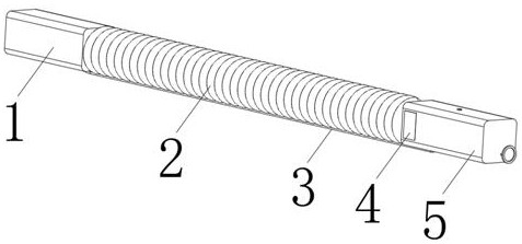
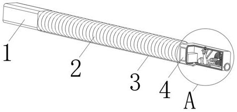
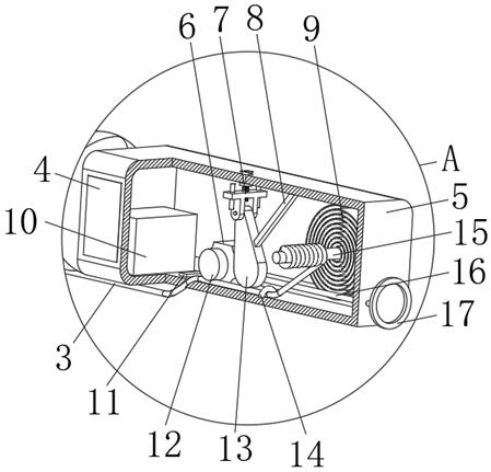
[0030] Example 1: Please refer to Figure 1-4 , this embodiment discloses a slow-release arm bar, which includes a handle 1, a spring 2, and a hollow handle 2 5. A cross bar 15 is arranged inside the handle 2 5, and the cross bar 15 rotates around its own axis. The two ends of the rod 15 are rotationally connected with the inner wall of the handle 2 5 through bearings or draw-in slots, the cross bar 15 is fixedly connected with the inner end of the scroll spring 9, and the outer end of the scroll spring 9 is fixedly connected with the inner wall of the handle 2 5 .
[0031] The present embodiment also comprises connecting rope 3, elastic part 8, rotating plate 13 and connecting piece, and handle two 5 outsides are provided with perforation near the position of spring 2, and one end of connecting rope 3 is wound on cross bar 15, and connecting rope 3 The other end passes through the perforation and is connected with handle one 1 .
[0032] One end of rotating plate 13 is conn...
Embodiment 2
[0040] Embodiment two: if image 3 As shown, this embodiment discloses a slow-release arm bar, the structure of which is roughly the same as that of Embodiment 1, the difference is that this embodiment also includes a buckle bar 14 located between the rotating plate 13 and the cross bar 15 , The buckle bar 14 is fixed on the inner wall of the handle two 5, and a hole is formed between the buckle bar 14 and the inner wall of the handle two 5, and the connecting rope 3 passes through the hole.
[0041] The working process and principle of this embodiment are: the buckle 14 presses the connecting rope 3 on the inner wall of the handle 2 5 to ensure that when the connecting rope 3 is pulled out from the handle 2 5, the contact between the rotating plate 13 and the connecting rope 3 Sufficient, and the frictional force when connecting rope 3 is tightened up is less than the frictional force when unwinding rope.
Embodiment 3
[0042] Embodiment three: as figure 1 , figure 2 and image 3 As shown, this embodiment discloses a slow-release arm force rod, the structure of which is roughly the same as that of Embodiment 1, the difference is that this embodiment also includes a pull cord 16 and a handle 2 on the side away from the spring 2. Draw ring 17, one end of stay cord 16 is fixedly connected with draw ring 17, and the other end of stay cord 16 runs through handle 2 5 and is fixedly connected with the outside of rotating plate 13.
[0043] The working process and principle of this embodiment are: when the connecting rope 3 is pulled out from the inside of the handle 25, the friction between the rotating plate 13 and the connecting rope 3 is too large, causing the spring 2 to fail to return to the natural state. Ring 17 pulls stay cord 16, and stay cord 16 pulls rotating plate 13 to rotate, and the frictional force between rotating plate 13 and connecting rope 3 becomes smaller, and spring 2 returns...
PUM
 Abstract
Description
Claims
Application Information
 - R&D
- Intellectual Property
- Life Sciences
- Materials
- Tech Scout
- Unparalleled Data Quality
- Higher Quality Content
- 60% Fewer Hallucinations
Browse by: Latest US Patents, China's latest patents, Technical Efficacy Thesaurus, Application Domain, Technology Topic, Popular Technical Reports.
© 2025 PatSnap. All rights reserved.Legal|Privacy policy|Modern Slavery Act Transparency Statement|Sitemap|About US| Contact US: help@patsnap.com


