A kind of electronic connector assembly equipment

A technology for electronic connectors and assembling equipment, which is applied in the direction of connection, assembly/disassembly of contacts, circuit/current collector components, etc. problems, to save finishing time, improve assembly quality and assembly efficiency, and improve stability

Active Publication Date: 2021-02-02
深圳市深凯精密五金有限公司
View PDF4 Cites 0 Cited by
  • Summary
  • Abstract
  • Description
  • Claims
  • Application Information

AI Technical Summary

Problems solved by technology

At present, the following problems exist in the assembly process of electronic connectors: (1) At present, the pins are collected uniformly after cutting the pin strips, and then assembled with the insulating base later, the process is complicated and the assembly efficiency is reduced; (2) In the During the pin conveying process, since the pin strip cannot be fixed well, and the cutting alignment is not high, it is prone to cutting deviation or the pins cannot be cut well; (3) when the pins are In the process of inserting into the insulating base, the existing equipment can only be assembled with a single pin, which requires multiple steps to be repeated, which affects the assembly efficiency; (4) At present, the electronic components are assembled and then conducted, so that It needs to waste a lot of time, and it is easy to cause scrap during the transportation process; (5) At present, before the shell is assembled, there is no detection function, so that the product is assembled and then tested, if scrapping occurs, the cost will increase; (6) The shell and During the riveting process of the insulating base, the stability of the riveting is poor, which affects the quality and efficiency of the riveting
Especially during the assembly process of the insulating base and the contact pins, the transportation of the insulating base is not smooth, and the contact strips cannot be clamped and fixed, causing the contact strips to move during cutting, and the cutting rod cannot be used for a period of time. Alignment, it is easy to have cutting deviation during cutting, resulting in low cutting accuracy, resulting in scrapped pins; multiple pins need multiple devices to be inserted into the pin slots of the insulating base multiple times, and the alignment accuracy is relatively low Low, resulting in a low degree of assembly between the pin and the insulating base, affecting the insertion quality and insertion efficiency

Method used


Image

  • A kind of electronic connector assembly equipment
  • A kind of electronic connector assembly equipment
  • A kind of electronic connector assembly equipment

Examples


Embodiment Construction

[0026] The specific implementation manner of the present invention will be described in detail below in conjunction with the accompanying drawings.

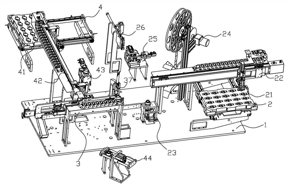
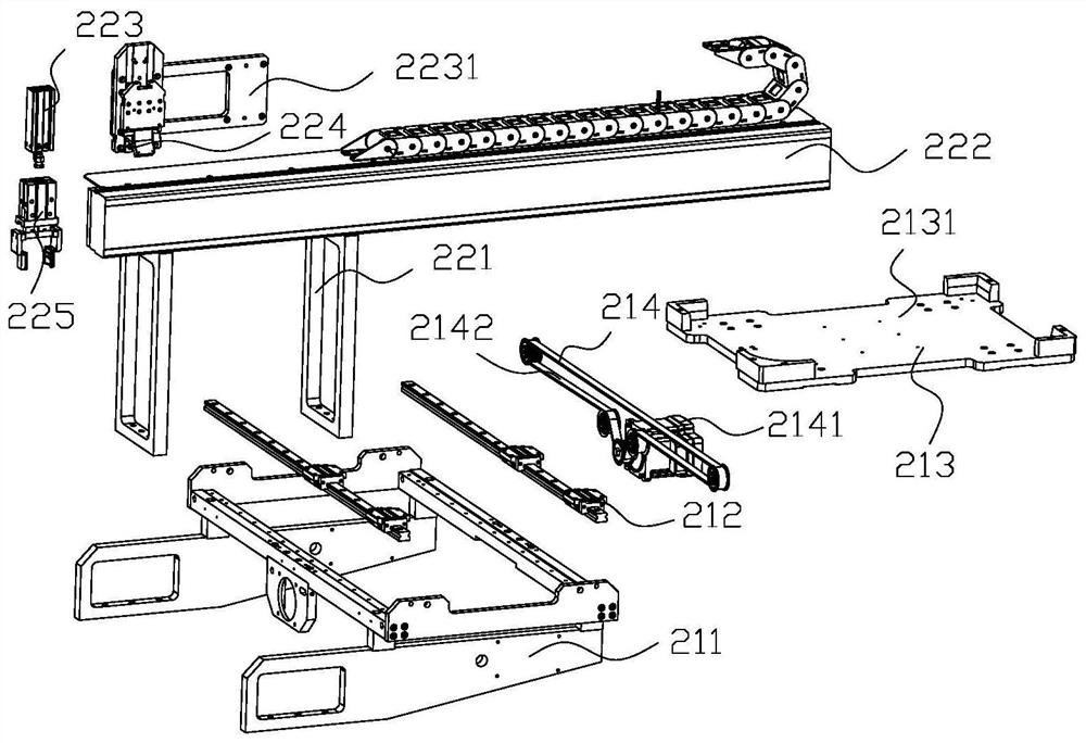
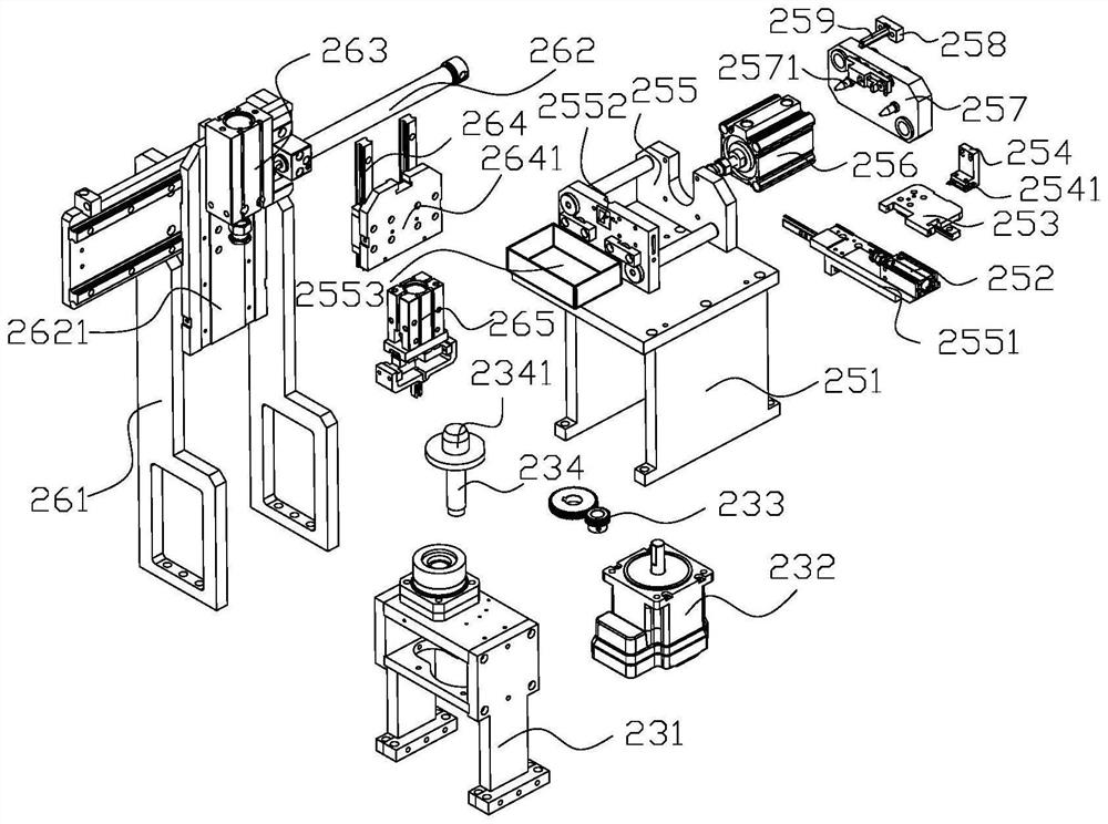
[0027] like figure 1 As shown, an electronic connector assembly equipment includes a frame 1 and a pin assembly device 2 installed thereon, a transfer conveying device 3 and a housing assembly device 4 . The pin assembly device 2 is used to directly assemble the pins with the insulating base after cutting; the pin assembling device 2 includes an insulating base feeding component 21, an insulating base transfer component 22, an insulating base and a pin assembly support Component 23, pin feeding carrier tape 24, pin cutting component 25 and pin transfer component 26; insulating base feeding component 21, insulating base transferring component 22, insulating base and pin assembly support component 23, The pin feeding carrier tape 24, the pin cutting assembly 25 and the pin transfer assembly 26 are respectively arranged on the fram...


PUM


Abstract

The invention relates to the field of electronic components. An electronic connector assembly equipment, including a frame and a pin assembly device installed on it, a transfer conveying device and a shell assembly device; the pin assembly device is used to directly assemble the pins with the insulating base after cutting; The transfer conveying device is used to transfer the assembly of the insulating base and pins to the shell assembly device, and the shell assembling device is used to assemble the assembly of the insulating base and pins with the shell, and transfer it through the transfer conveyor after assembly Convey the blanking. The advantage of this patent is that the contact pin is directly assembled with the insulating base after cutting, and the assembly quality of the contact pin and the shell and the insulating base is improved.

Description

technical field [0001] The invention relates to the field of electronic components, in particular to an electronic connector and its assembly method and equipment. Background technique [0002] Electronic components, especially various electronic connectors, are usually formed by assembling an insulating base and a plurality of metal pins. The pin is a metal substance used to complete the conductive transmission of electrical signals in the connector. The assembly method of the pin and the insulating base is generally inserted. Insertion refers to inserting the pins into the preset holes of the insulating base. Current electronic components are fitted with metal casings on top of insulating bases, which are used for added strength and protection. During the assembly process of the electronic connector, it is necessary to insert multiple pins into the preset multiple pin slots on the upper part of the insulating base, and then assemble the assembly of the pins and the insul...

Claims


Application Information

Patent Timeline
Patent Type & Authority Patents(China)
IPC IPC(8): H01R43/048H01R43/052H01R43/055H01R43/20H01R43/28
CPCH01R43/048H01R43/052H01R43/055H01R43/20H01R43/28
Inventor 楼显华沈杭杰朱仁康
Owner 深圳市深凯精密五金有限公司
Why Eureka
Try Eureka