Novel carbon dioxide liquefaction device and preparation method

A carbon dioxide and liquefaction device technology, applied in liquefaction, refrigeration and liquefaction, lighting and heating equipment, etc., can solve the problems of violent boiling, affecting heat exchange effect, unstable liquid level, etc., to improve the cooling capacity conversion rate, Small footprint and small equipment investment

Active Publication Date: 2020-06-23
HUIZHOU HUA DA TONG GAS MFG CO LTD
View PDF6 Cites 0 Cited by
  • Summary
  • Abstract
  • Description
  • Claims
  • Application Information

AI Technical Summary

Problems solved by technology

The current carbon dioxide liquefaction process is that liquid ammonia enters the shell side of the carbon dioxide liquefier through the pipeline and the regulating valve, and the regulating valve controls the liquid level. The liquid ammonia is decompressed and gasified at the shell side of the carbon dioxide liquefier, and the gas will occupy most of the heat exchange area. As a result, the equipment will be very large, and at the same time, the liquid ammonia and gas ammonia that have just come in will become overheated, which will affect the heat exchange effect
The liquid level in the shell side of the traditional carbon dioxide liquefier is unstable, the liquid level fluctuates greatly, there is liquid overheating, and violent boiling often occurs

Method used


Image

  • Novel carbon dioxide liquefaction device and preparation method

Examples


Embodiment Construction

[0019] The technical solutions in the embodiments of the invention will be clearly and completely described below in conjunction with the drawings in this embodiment.

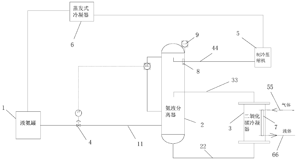
[0020] See figure 1 As shown, the present invention also provides a new type of carbon dioxide liquefaction device, including a liquid ammonia tank 1, an ammonia separator 2 and a carbon dioxide condenser 3. The liquid ammonia in the liquid ammonia tank is transported through a first pipe 11 through a regulating valve 4 Sent to the bottom of the ammonia separator, the bottom of the ammonia separator transports the liquid ammonia to the bottom of the carbon dioxide condenser through the second pipe 22; the heat exchange and temperature rise vaporized liquid ammonia in the carbon dioxide condenser faces downward through the elbow opening The third pipe 33 is delivered to the middle inlet valve of the ammonia separator; the ammonia in the upper part of the ammonia separator chamber is delivered to the inlet of the re...


PUM


Abstract

The invention discloses a novel carbon dioxide liquefaction device and preparation method. The device comprises a liquid ammonia tank, an ammonia-liquid separator and a carbon dioxide condenser; liquid ammonia in the liquid ammonia tank is conveyed to the bottom of the ammonia-liquid separator through a first pipeline by means of a regulating valve, and the bottom of the ammonia-liquid separator conveys the liquid ammonia to the bottom of the carbon dioxide condenser through a second pipeline; the liquid ammonia gasified by heat exchange and temperature rise in the carbon dioxide condenser isconveyed to a middle inlet valve of the ammonia-liquid separator through a third pipeline; ammonia gas at the upper part of a chamber of the ammonia-liquid separator is conveyed to an inlet of a refrigeration compressor through a fourth pipeline, and the ammonia gas circularly flows back to the liquid ammonia tank through an evaporation type condenser in sequence; and an aluminum finned plate heatexchanger is arranged in the carbon dioxide condenser, and gaseous carbon dioxide enters the aluminum finned plate heat exchanger from an upper pipeline and is condensed and then comes out from a lower pipeline. The integrated equipment is small in occupied space, the cold energy conversion rate is high, stable liquid level can be ensured, and overheating boiling can be avoided.

Description

Technical field [0001] This solution belongs to the field of refrigeration technology, and specifically relates to a carbon dioxide liquefaction device. Background technique [0002] The volume of the existing carbon dioxide liquefaction device is relatively huge, which reduces the space utilization rate. The installation method is a flat layout, which does not fully save space, and the conversion rate of cold energy is not high. The current carbon dioxide liquefaction process is that liquid ammonia enters the shell side of the carbon dioxide liquefier through a pipeline and a regulating valve. The regulating valve controls the liquid level. The liquid ammonia is vaporized under reduced pressure in the shell side of the carbon dioxide liquefier. The gas will occupy most of the heat exchange area. As a result, this equipment will be very large, and at the same time, the liquid ammonia and gas ammonia that have just entered will become overheated, which will affect the heat exchang...

Claims


Application Information

Patent Timeline
Patent Type & Authority Applications(China)
IPC IPC(8): F25J1/00
CPCF25J1/0027F25J1/0204F25J1/0257
Inventor 石唯曾杨文刘峰
Owner HUIZHOU HUA DA TONG GAS MFG CO LTD
Why Eureka
Try Eureka