Anti-winding ship shaft

An anti-winding and main shaft technology, which is applied in the direction of mechanical gear transmission, transmission with synchronous propulsion components, water action propulsion components, etc., can solve the problem of increased resistance of the shaft transmission and achieve the effect of solving foreign matter entanglement

Active Publication Date: 2020-06-26
涡阳县信隆船舶附件有限公司
View PDF7 Cites 2 Cited by
  • Summary
  • Abstract
  • Description
  • Claims
  • Application Information

AI Technical Summary

Problems solved by technology

Once the shaft is entangled by foreign objects, the resistance of the shaft transmission will increase significantly

Method used


Image

  • Anti-winding ship shaft
  • Anti-winding ship shaft

Examples


Embodiment Construction

[0015] In order to make the object, technical solution and advantages of the present invention clearer, the present invention will be described in further detail below in conjunction with specific embodiments and with reference to the accompanying drawings.

[0016] It should be noted that all expressions using "first" and "second" in the embodiments of the present invention are to distinguish two entities with the same name but different parameters or parameters that are not the same, see "first" and "second" It is only for the convenience of expression, and should not be understood as limiting the embodiments of the present invention. In addition, the terms of direction and position mentioned in the present invention, such as "upper", "middle", "lower", "front", "rear", "Left", "right", "inner", "outer", "side", etc., are only referring to the directions and positions of the attached drawings. Therefore, the terms of directions and positions used are for explaining and unders...


PUM


Abstract

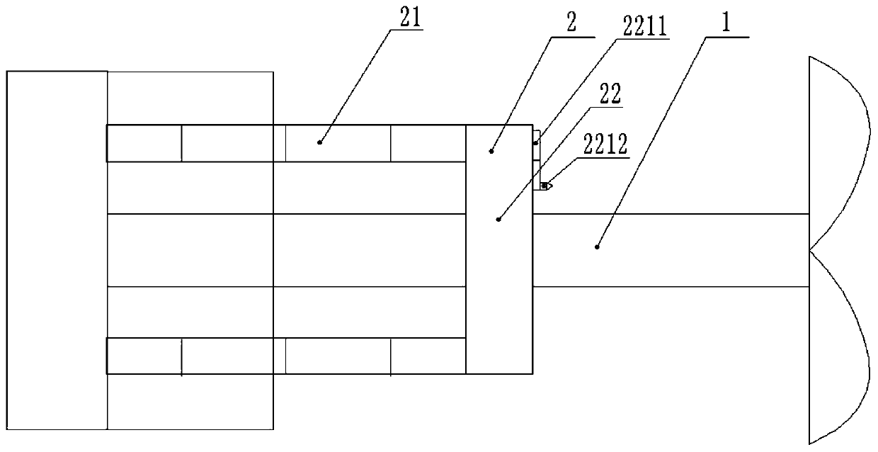
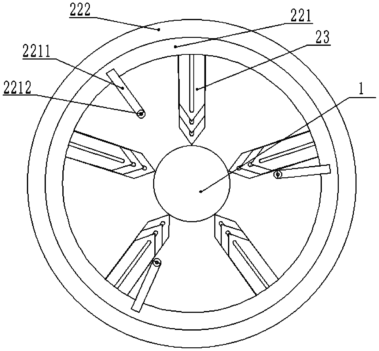
The invention discloses an anti-winding ship shaft, relates to the technical field of ship shafts, and aims to solve the technical problem that a ship shaft is wound by foreign matters. The anti-winding ship shaft comprises a main shaft arranged on a ship body and a cutting module arranged on the ship body and sleeving the main shaft; the splitting module comprises a telescopic rod arranged on theship body, a lantern ring arranged on the telescopic rod and a cutting knife arranged on the inner side of the lantern ring; the axis of the telescopic rod is parallel to the axis of the main shaft;the lantern ring is sleeved on the main shaft, and the axis of the lantern ring coincides with the axis of the main shaft; one end of the cutter is arranged inside the lantern ring, and the other endis close to the outer surface of the main shaft. Through the arrangement of the cutting module, when the telescopic rod drives the lantern ring to move along the main shaft, the cutting knife on the inner side of the lantern ring can cut off foreign matter frequently wound on the main shaft, and the technical problem that the ship shaft is wound by the foreign matter is effectively solved.

Description

technical field [0001] The invention relates to the technical field of ship shafts, in particular to an anti-winding ship shaft. Background technique [0002] The ship's shaft is the transmission part of the ship, protruding out of the hull and transmitting the driving force to the propeller. Once the shaft is entangled by foreign matter, the resistance of the shaft transmission will increase significantly. Contents of the invention [0003] In view of this, the object of the present invention is to propose an anti-winding ship shaft, so that through the setting of the splitting module, when the telescopic rod moves along the main shaft with the collar, the cutting knife inside the collar will split and often stay on the main shaft. The foreign matter effectively solves the technical problem that the shaft of the ship is entangled by foreign matter. [0004] Based on the above purpose, the present invention provides an anti-winding ship shaft, the anti-winding ship shaft...

Claims


Application Information

Patent Timeline
Patent Type & Authority Applications(China)
IPC IPC(8): B63H23/02B63H23/04B63H23/34
CPCB63H23/02B63H23/04B63H23/34
Inventor 王苗苗蔡龙赐张飞达
Owner 涡阳县信隆船舶附件有限公司
Why Eureka
Try Eureka