A ship shaft stabilizing and damping device

A shock absorbing device, a stable technology, applied in the direction of spring/shock absorber, mechanical gear transmission, transmission with synchronous propulsion components, etc., can solve the bending stress fatigue damage of the ship shaft, limited shock absorption effect of the ship shaft, and influence Issues such as ship propulsion characteristics and stable navigation

Active Publication Date: 2020-12-25
涡阳县信隆船舶附件有限公司
View PDF8 Cites 0 Cited by
  • Summary
  • Abstract
  • Description
  • Claims
  • Application Information

AI Technical Summary

Problems solved by technology

[0002] The ship's shaft is the power shaft of the ship. Generally, the driving force of the driving mechanism drives the ship's shaft to rotate at a high speed to drive the outer propeller of the ship to rotate to realize the ship's motion. Therefore, the ship's shaft is one of the important components of the ship's power device. The ship's shaft The quality of the work will directly affect the propulsion characteristics and normal navigation of the ship. However, when the ship shaft rotates to propel the ship to run, due to the impact of the uneven water flow field on the propeller, as well as the inevitable vibration of the drive mechanism and the transmission system itself The common influence, coupled with the high-speed rotation of the ship shaft itself, inevitably generates vibration, and the vibration problem of the high-speed rotating device has always been a prominent and difficult to solve problem. The existing anti-vibration of the ship shaft is generally by reducing the shaking of the driving mechanism , in order to reduce the shaking force transmitted to the ship shaft, the general method is to strengthen the driving mechanism and use springs or shock absorbers to achieve it. However, the shock absorption effect on the ship shaft is limited, thus affecting the propulsion characteristics and stable navigation of the ship, and even Cause the ship shaft to be damaged by bending stress fatigue for a long time

Method used


Image

  • A ship shaft stabilizing and damping device
  • A ship shaft stabilizing and damping device

Examples


Embodiment Construction

[0026] In order to make the object, technical solution and advantages of the present invention clearer, the present invention will be described in further detail below in conjunction with specific embodiments and with reference to the accompanying drawings.

[0027] It should be noted that all expressions using "first" and "second" in the embodiments of the present invention are to distinguish two entities with the same name but different parameters or parameters that are not the same, see "first" and "second" It is only for the convenience of expression, and should not be construed as a limitation on the embodiments of the present invention, which will not be described one by one in the subsequent embodiments.

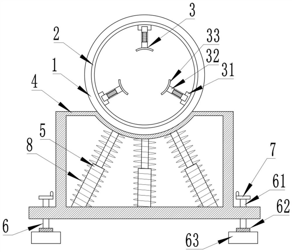
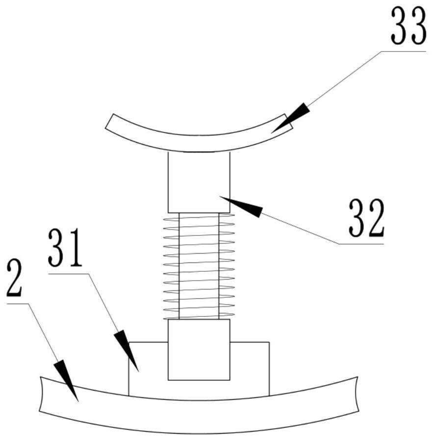
[0028] A ship shaft stabilizing shock-absorbing device, such as Figure 1 to Figure 2 As shown, the damping chamber 1 is included, and the damping chamber 1 is designed as a hollow cylindrical cavity in the axial direction, which is used to be sleeved on the shaft of ...


PUM


Abstract

The invention discloses a ship shaft stabilizing and damping device. The ship shaft stabilizing and damping device device comprises a damping chamber, a sliding rail is fixedly arranged on the inner wall of the damping cavity in the circumferential direction. Three groups of damping mechanisms are arranged; each damping mechanism comprises a sliding block, a spring telescopic rod and a rubber damping pad. The spring telescopic rods rotate to adjust the length, therefore, the rubber damping pads are tightly pressed on the outer side wall of the ship shaft in an attached mode. The directions ofthe three groups of damping mechanisms are adjusted, the damping mechanisms are attached to the outer side wall of the ship shaft in a triangular shape. When the ship shaft rotates, meanwhile, the damping mechanisms can be driven to rotate along the sliding rail; the spring telescopic rods and the rubber shock pads are used for buffering and attenuating the vibration energy of the ship shaft; thebase used for supporting and erecting are arranged, the hydraulic damper is fixed in the hollow interior of the base so as to play a role in stabilizing and damping, the height of the base can be adjusted through the height adjusting mechanism, the ship shaft stabilizing and damping device is used for more comprehensively damping a ship shaft while rotating of the ship shaft is not affected, and the ship shaft stabilizing and damping device can be suitable for ship shafts of different sizes.

Description

technical field [0001] The invention relates to the technical field of ship shafts, in particular to a ship shaft stabilization and shock absorbing device. Background technique [0002] The ship's shaft is the power shaft of the ship. Generally, the driving force of the driving mechanism drives the ship's shaft to rotate at a high speed to drive the outer propeller of the ship to rotate to realize the ship's motion. Therefore, the ship's shaft is one of the important components of the ship's power device. The ship's shaft The quality of the work will directly affect the propulsion characteristics and normal navigation of the ship. However, when the ship shaft rotates to propel the ship to run, due to the impact of the uneven water flow field on the propeller, as well as the inevitable vibration of the drive mechanism and the transmission system itself The common influence, coupled with the high-speed rotation of the ship shaft itself, inevitably generates vibration, and the ...

Claims


Application Information

Patent Timeline
Patent Type & Authority Patents(China)
IPC IPC(8): B63H23/04B63H23/34F16F15/023F16F15/08F16F15/123F16F15/124
CPCB63H23/04B63H23/34F16F15/022F16F15/023F16F15/08F16F15/1201F16F15/1207F16F15/12306F16F15/124
Inventor 王苗苗蔡龙赐张飞达
Owner 涡阳县信隆船舶附件有限公司
Why Eureka
Try Eureka