Automatic robot spraying device

An automatic spraying and robot technology, applied in spraying devices, liquid spraying devices, etc., can solve the problems of poor paint atomization, poor workpiece, and poor spraying effect, and achieve uniform spray paint thickness, good processing effect, and uniform spray range. Effect

Pending Publication Date: 2020-07-03
翰贝摩尔表面技术(江苏)有限公司
View PDF0 Cites 12 Cited by
  • Summary
  • Abstract
  • Description
  • Claims
  • Application Information

AI Technical Summary

Problems solved by technology

[0004] The purpose of the present invention is to provide a robot automatic spraying device to solve the problem that the air flow in the nozzle and the paint in the noz

Method used


Image

  • Automatic robot spraying device
  • Automatic robot spraying device
  • Automatic robot spraying device

Examples


Embodiment

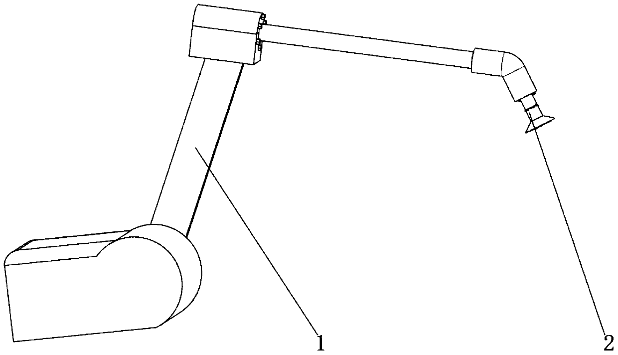
[0024] see Figure 1-4 , the present invention provides a technical solution: a robot automatic spraying device, including a robot main body 1, a spraying mechanism 2 is provided on one side of the robot main body 1,

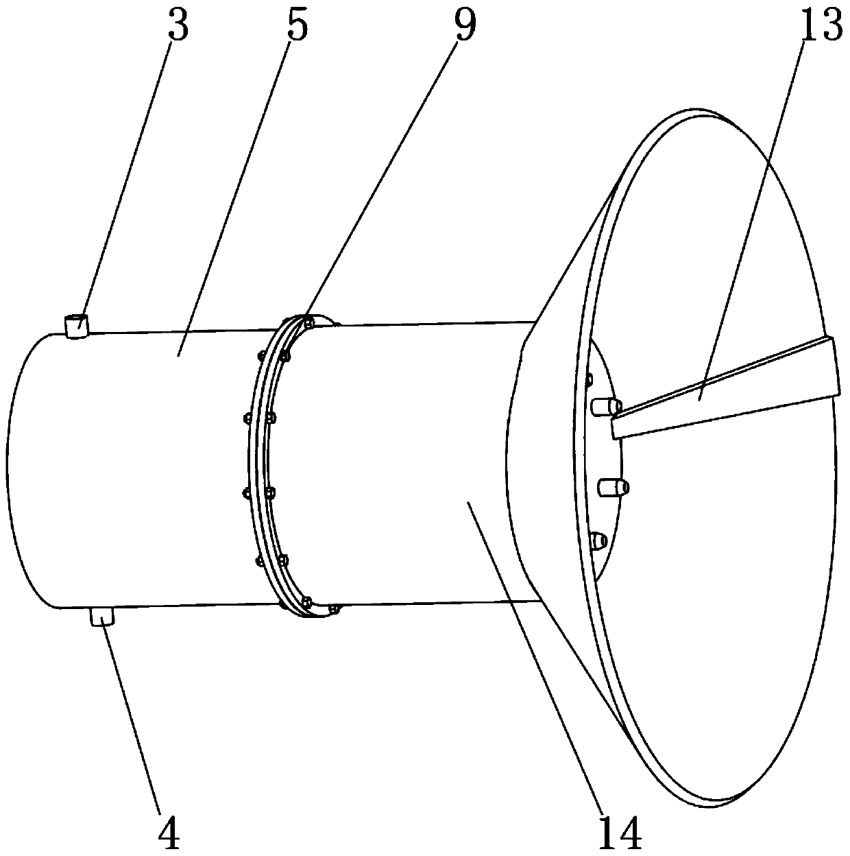
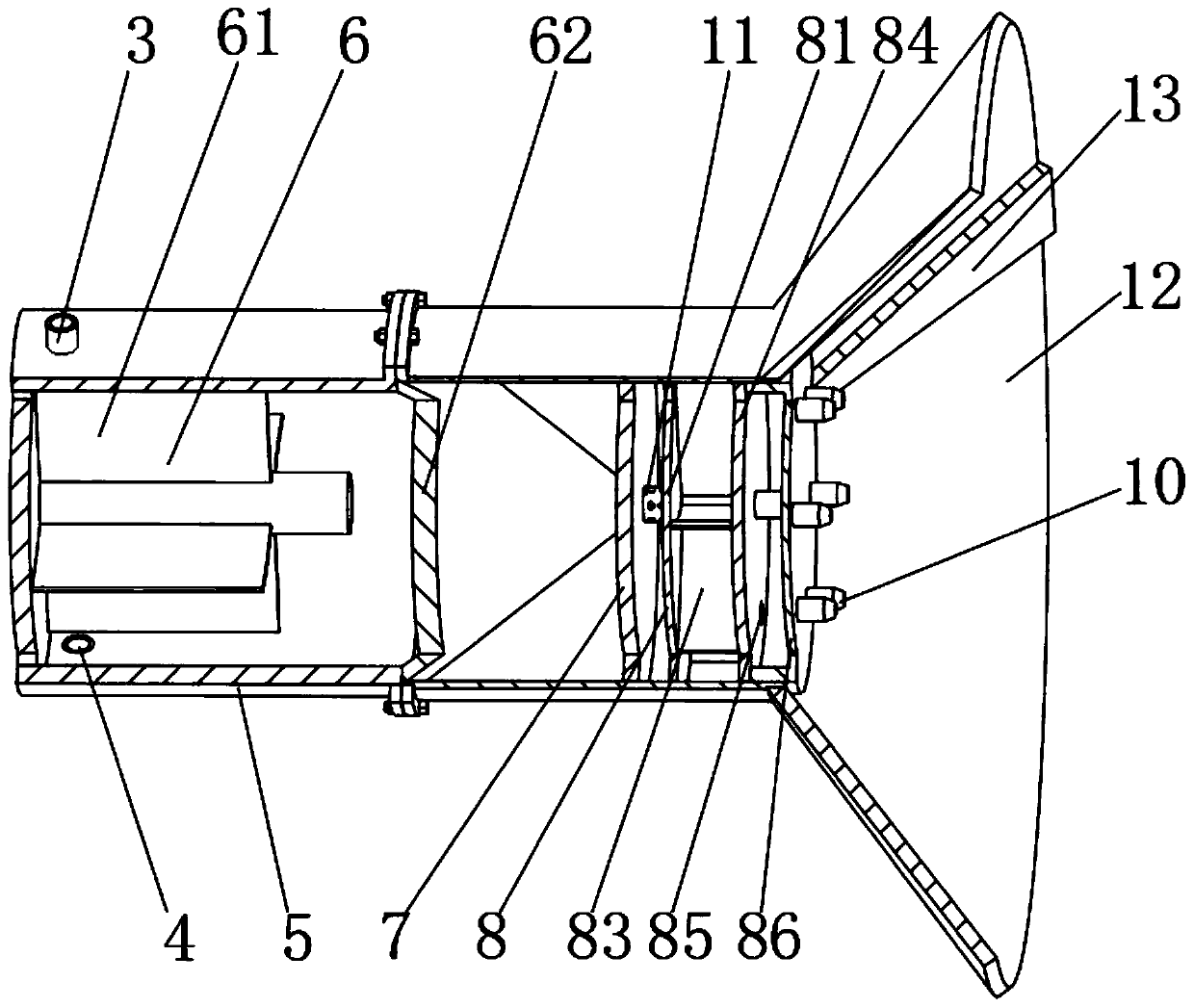
[0025] The ejection mechanism 2 includes a base 5 fixedly connected to the robot main body 1. The inside of the base 5 is provided with a mixing mechanism 6. The surface of the base 5 is respectively provided with a gas pipe port 3 and a spray paint inlet 4. Specifically, the air pipe port 3 and the paint spray inlet 4 They are respectively fixedly connected with the base 5 and internally communicated. One side of the base 5 is provided with a mounting base 14, and the mounting base 14 and the base 5 are connected by bolts 9. Specifically, flanges are provided on the opposite surfaces of the mounting base 14 and the base 5. , the mounting seat 14 and the flange of the base 5 are detachably connected by bolts 9,

[0026] The inside of the installation seat 14 is...


PUM


Abstract

The invention relates to an automatic robot spraying device which comprises a robot body. A spraying mechanism is arranged on one side of the robot body and comprises a base fixedly connected with therobot body, a mixing mechanism is arranged in the base, an air pipe opening and a paint spraying inlet are formed in the surface of the base, a mounting base is arranged on one side of the base, andthe mounting base and the base are connected through bolts. Compared with the prior art that in the using process of a spray head, air flow and paint in the spray head are possibly not mixed uniformlyenough, so that the spraying effect is poor, the atomization effect of the paint is poor, and consequently a workpiece is poor, the device has the beneficial effect that the air flow is used as powerto drive mixing blades to rotate, the gas and the paint are driven to be completely mixed, the atomization effect is good when the paint is sprayed out, and the workpiece spraying effect is good.

Description

technical field [0001] The invention relates to the technical field of spraying equipment, in particular to a robotic automatic spraying device. Background technique [0002] Spraying is a coating method in which spray guns or disc atomizers are dispersed into uniform and fine droplets by means of pressure or centrifugal force and applied to the surface of the object to be coated. It can be divided into air spraying, airless spraying, electrostatic spraying and various derived methods of the above basic spraying forms, such as large flow and low pressure atomization spraying, thermal spraying, automatic spraying, multi-group spraying, etc. [0003] When spraying the workpiece, use the nozzle to spray the paint directly. During the use of the nozzle, the airflow in the nozzle may not be mixed evenly with the paint, resulting in poor spraying effect and poor atomization effect of the paint, which will lead to poor workpiece. , The paint nozzle is in a fixed state. When sprayi...

Claims


Application Information

Patent Timeline
IPC IPC(8): B05B7/04B05B12/08B05B12/16B05B13/04B05B15/25
CPCB05B7/0416B05B12/084B05B12/16B05B13/0421B05B15/25
Inventor 朱秋日
Owner 翰贝摩尔表面技术(江苏)有限公司
Why Eureka
Try Eureka