Roller control switch

A technology for controlling switches and rollers, applied in electrical switches, electrical components, circuits, etc., can solve the problems of increasing the possibility of rollers, accidental triggering, inconvenient operation, etc., to reduce the possibility of false triggering, obvious operation feeling, and processing handy effect

Pending Publication Date: 2020-07-03
TRW AUTOMOTIVE COMPONENTS SUZHOU
View PDF1 Cites 0 Cited by
  • Summary
  • Abstract
  • Description
  • Claims
  • Application Information

AI Technical Summary

Problems solved by technology

[0004] However, the roller control switch in the prior art, including the roller motion recognition device disclosed in the above-mentioned patent, has a rolling shaft with a structure supported at both ends, so the roller can only be buried in the casing, and only part of it leaks out. There is no one at present. One end or the whole of the roller can protrude from the outside of the casing and the roller control switch can realize various control functions
[0005] In addition, the technical solutions in the above-mentioned patent documents still have certain defects. First, because the outer surface of the roller is only partly exposed outside the casing, the exposed part can only be turned or pressed by fingers during use. , when the roller is turned, the friction between the finger and the surface of the roller is mainly used to drive the roller to rotate, so it is difficult to control the roller and the operation is inconvenient; secondly, it is easy to press the roller while turning the roller during operation, resulting in other functions. Accidentally triggered, especially when it is also equipped with supporting shrapnel to block the roller, the rotation resistance of the roller will increase significantly. To drive the roller to rotate manually, only greater force can be applied, which greatly increases the possibility of the roller being depressed. In addition, because the micro switch is set under the roller, and the stroke of the micro switch is limited, which limits the distance that needs to be pressed down to trigger the micro switch, so that a small pressing range may trigger the micro switch, resulting in operation Poor feel, further exacerbating the possibility of depressing the microswitch when turning the scroll wheel

Method used


Image

  • Roller control switch
  • Roller control switch
  • Roller control switch

Examples


Embodiment Construction

[0034] The technical solution of the present invention will be described in further non-limiting detail below in combination with preferred embodiments and accompanying drawings.

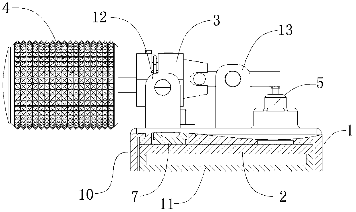
[0035] like figure 1 As shown, the roller control switch corresponding to a preferred embodiment of the present invention includes a base 1, and the base 1 includes an upper shell 10 and a lower shell 11 that are snap-fitted to each other. The circuit board 2 between the housing 10 and the lower housing 11.

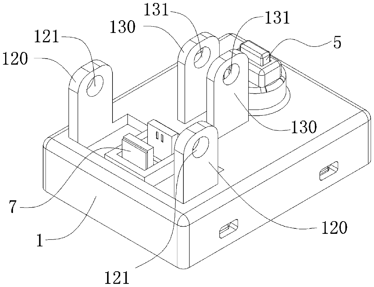
[0036] The base 1 is also provided with a first rotating shaft frame group 12 and a second rotating shaft frame group 13 protruding upward. further reference figure 2 , the first rotating shaft frame group 12 is provided with two first rotating shaft frames 120 which are arranged oppositely, and the first rotating shaft holes 121 arranged on the same axis are opened on the two first rotating shaft frames 120; the second rotating shaft frame group 13 and the first rotating shaft frame The ro...


PUM


Abstract

The invention discloses a roller control switch. The roller control switch comprises a base, a rotating shaft assembly, a roller, a pressing switch and an optocoupler, wherein the pressing switch andthe optocoupler are installed on the base; the base comprises a first rotating shaft frame and a second rotating shaft frame which are arranged at intervals; the rotating shaft assembly comprises a driving shaft, a mounting frame rotatably connected with the first rotating shaft frame and a driven shaft rotatably connected with the second rotating shaft frame; the driven shaft is movably connectedwith the mounting frame; one end of the driving shaft is connected with the roller, and the other end of the driving shaft is rotatably connected with the mounting frame; the optocoupler detects therotation of the driving shaft; and the pressing switch is arranged in correspondence to the driven shaft, and the driven shaft can be driven to press the pressing switch by toggling the roller. The roller of the roller control switch can conveniently extend out of the outer shell, so operation is more convenient and comfortable, and other functions are not prone to being triggered by mistake.

Description

technical field [0001] The invention relates to a control switch, in particular to a roller control switch. Background technique [0002] With the development of automobile technology, people pay more and more attention to the comfort of car control. In order to facilitate the driver to control various functions of the car, and at the same time take into account the safety of the control switch during driving, more and more control switches are set. On the steering wheel of the car, a large number of control functions can be realized without leaving the steering wheel. [0003] Due to the various functions of the car and the limited space on the steering wheel, one control switch structure often needs to realize multiple function controls. For example, the Chinese invention patent with application number 201611153534.3 discloses a rolling wheel motion recognition device, which includes a rolling wheel, a rolling shaft following the rotation of the rolling wheel, and a splin...

Claims


Application Information

Patent Timeline
IPC IPC(8): H01H19/04H01H19/14
CPCH01H19/04H01H19/14
Inventor 王振兴刘曹阳陈进田涛
Owner TRW AUTOMOTIVE COMPONENTS SUZHOU
Why Eureka
Try Eureka