Laser discharge chamber device of gas CO2 laser

A laser and discharge cavity technology, applied in gas laser parts, laser parts and other directions, can solve the problems of increasing discharge transition probability, the inability of the laser to operate stably and reliably for a long time, and the inability to maintain the stability of glow discharge, etc. To achieve the effect of stable discharge duration, long discharge duration, and consistent discharge duration

Inactive Publication Date: 2009-09-23
CHANGCHUN INST OF OPTICS FINE MECHANICS & PHYSICS CHINESE ACAD OF SCI
View PDF0 Cites 13 Cited by
  • Summary
  • Abstract
  • Description
  • Claims
  • Application Information

AI Technical Summary

Problems solved by technology

As a result, it is impossible for high-power gas CO2 lasers to work stably and reliably for a long time. To solve the problem of photodischarge stability, laser discharge chambers composed of different types of discharge electrodes, pre-ionization methods, and gas circulation channels are

Method used


Image

  • Laser discharge chamber device of gas CO2 laser
  • Laser discharge chamber device of gas CO2 laser

Examples


Example Embodiment

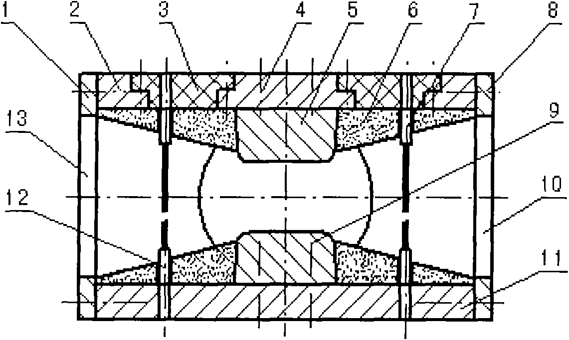
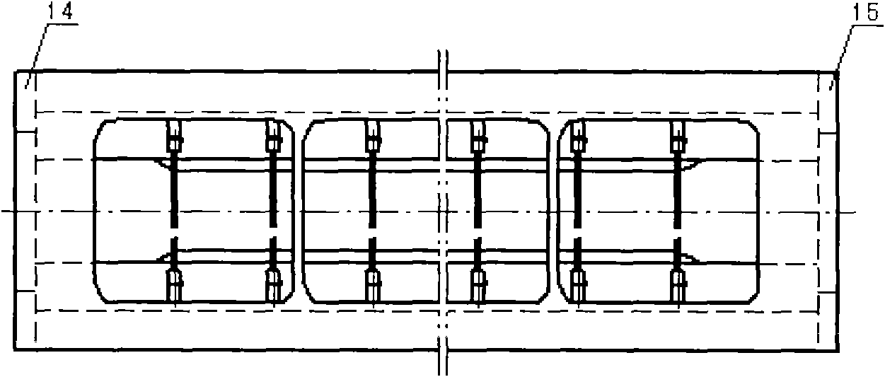
[0016] The present invention will be further described below with reference to the drawings and specific embodiments: see figure 1 with figure 2 :

[0017] The gas CO of the present invention 2 The laser discharge cavity includes the right side vertical plate 01, the upper cavity support frame plate 02, the cavity upper insulating frame plate 03, the cavity upper electrode plate 04, the upper discharge electrode 05, the ceramic insulating sheet 06, the upper pre-ionization trigger pin 07, the cavity Left vertical plate 08, lower discharge electrode 09, gas circulation channel inlet 10, cavity lower electrode plate 11, lower pre-ionization trigger needle 12, gas circulation channel outlet 13, cavity front end plate 14, cavity rear end The plate 15 constitutes a laser discharge cavity device.

[0018] The cavity right side vertical plate 01; the cavity left side vertical plate 08; the cavity front side end plate 14; the cavity back side end plate 15 is welded to form a frame by an ...


PUM


Abstract

The invention relates to a laser discharge chamber device of a gas CO2 laser, comprising a vertical plate at the right side of the chamber, a support frame plate on the chamber, an upper insulating frame plate on the chamber, an upper electrode plate, a ceramic insulating strip, an upper preionization triggering needle, a vertical plate at the left side of the chamber, a lower discharge electrode, the air inlet of a gas circulating path, a lower electrode plate, a lower preionization triggering needle, the air outlet of the gas circulating path, an end plate at the right side of the chamber and an end plate at the left side of the chamber. The device is characterized in that the laser discharge chamber is fixedly arranged on a sealed circulating work gas passage; electrical energy is injected by an energy-storing charge-discharge circuit so that the upper discharge electrode and the lower discharge electrode realizes even glow discharge in large area; and a plurality of pairs of upper ultraviolet light preionization triggering needles and lower ultraviolet light preionization triggering needles realize spark discharge to form the laser discharge chamber of the laser. The invention has small volume and compact structure, is convenient for repairing and installing the discharge electrode and the preionization triggering needles, leads a CO2 laser system to stably work for a long time so as to extend service life, and is fit for high-power gas lasers and pulse gas lasers.

Description

technical field [0001] The invention relates to a gas laser, in particular to gas TEA CO with high voltage, high current, high pulse energy and high repetition rate 2 Laser discharge chamber device for lasers. Background technique [0002] For continuous output CO 2 Laser or pulsed laser gas CO 2 All lasers require the laser discharge cavity to work in a uniform glow discharge state. In order to obtain higher power laser output, it is necessary to inject a large amount of electric energy into the laser discharge cavity through the energy storage charging and discharging system of the laser, and maintain a uniform field in the laser discharge cavity under a stable range of working gas pressure and high voltage and high current. Glow discharge to avoid the occurrence of arc discharge, which is a high-power gas CO 2 Lasers (especially pulsed gas CO 2 Laser) technology is difficult to solve the key problems. Due to the laser discharge process, there are transition factors ...

Claims


Application Information

Patent Timeline
IPC IPC(8): H01S3/03
Inventor 耿玉民郭劲
Owner CHANGCHUN INST OF OPTICS FINE MECHANICS & PHYSICS CHINESE ACAD OF SCI
Why Eureka
Try Eureka