Applicator comprising an integrated control circuit

A technology for controlling circuits and applicators, applied in the directions of circuits, electromagnets, electrical components, etc., to achieve the effect of not easy to interrupt, reduce current, and reduce the number of wires

Active Publication Date: 2020-07-03
DUERR SYST GMBH
View PDF11 Cites 1 Cited by
  • Summary
  • Abstract
  • Description
  • Claims
  • Application Information

AI Technical Summary

Problems solved by technology

[0020] However, this known arrangement has the

Method used


Image

  • Applicator comprising an integrated control circuit
  • Applicator comprising an integrated control circuit
  • Applicator comprising an integrated control circuit

Examples


Example Embodiment

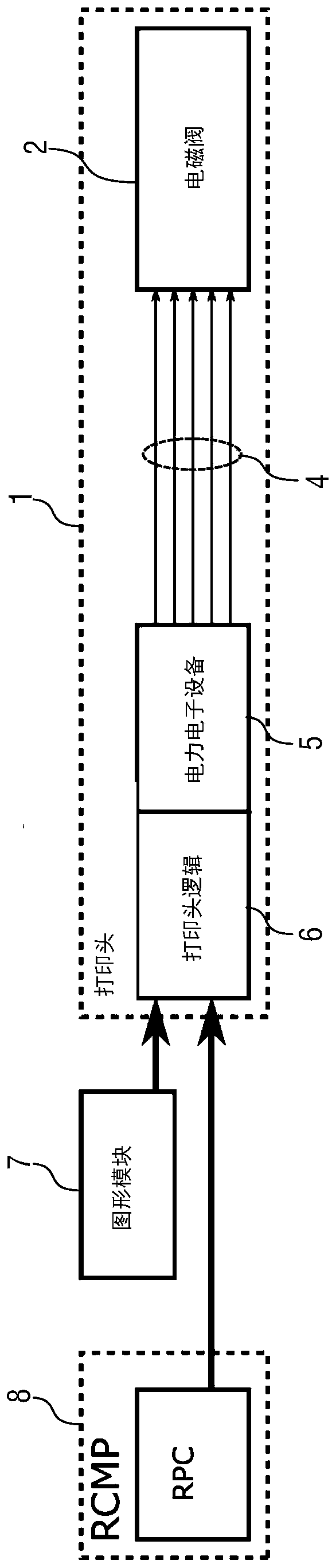
[0079] figure 2 A schematic diagram of a painting device based on the present invention is shown. For example, the painting device can be used to paint a car body component. This embodiment according to the present invention partially corresponds to the expression described above and shown in FIG. 1, so to avoid repetition, reference is made to the above description, whereby the same reference numerals are used for corresponding details.

[0080] A special feature of this embodiment is that the print head logic 6 and the power electronics 5 are integrated in the print head 1.

[0081] On the one hand, this has the following advantages: the line 4 between the power electronic device 5 and the solenoid valve 2 is less likely to be interrupted.

[0082] On the other hand, the line between the power electronic equipment 5 and the solenoid valve 2 is also less sensitive to interference EMC emissions from the outside.

[0083] Another advantage is that the line between the power electronic ...


PUM


Abstract

The invention relates to an applicator (1), in particular a printhead (1), for applying a coating agent, in particular a paint, to a component, in particular to a motor vehicle body component or an add-on part for a motor vehicle body component, the applicator (1) comprising a plurality of nozzles for applying the coating agent in the form of a coating agent jet, further comprising a plurality ofcoating agent valves (2) for controlling the dispensing of the coating agent through the individual nozzles, and comprising a plurality of electrically controllable actuators for controlling the coating agent valves (2). According to the invention, a control circuit (5, 6) for electrically controlling the actuators is integrated into the applicator (1).

Description

technical field [0001] The present invention relates to an applicator (eg, a printhead) for applying a coating agent (eg, paint) to a component (eg, a motor vehicle body component or an additional part of a motor vehicle body component). Background technique [0002] The operating principle of known existing drop-on-demand printheads (eg US 9108424 B2) is based on the use of solenoid valves. A magnetic piston (valve needle) is guided in the coil and lifted into the coil by a current source. This frees the valve opening, and depending on the opening time, fluid (eg, ink) can escape as ink droplets or as "jet portions" of various sizes. [0003] In the case of existing printheads, both the power electronics and the printhead logic are mounted externally to the printhead. Power electronics are used to generate the voltage and current required to operate the solenoid valves, while the printhead logic is used to determine the switching times of individual solenoid valves accord...

Claims


Application Information

Patent Timeline
IPC IPC(8): B05B12/04B05B1/30H01F7/06B05B13/04
CPCB05B1/3053B05B12/04B05B13/0452H01F7/1883B41J2/04B41J2/04581B25J11/0075B41J2002/041B41J2002/14475B41J2202/05B41J2/14
Inventor H-G·弗里茨B·沃尔M·克莱纳M·布贝科T·贝尔F·赫勒S·索茨尼D·坦德勒T·贝恩特A·盖格尔
Owner DUERR SYST GMBH
Why Eureka
Try Eureka