
A clean anti-overflow electric rice cooker

An electric rice cooker and cleaning technology, which is applied in the field of clean anti-overflow electric rice cooker, can solve the problems of poor anti-overflow function, reduce the cooking efficiency of the electric cooker, increase the difficulty of cleaning the cooker body, etc., so as to reduce the heat loss, improve the cleaning performance, and improve the cleanliness. performance effect

Active Publication Date: 2021-12-10
王冬芳
View PDF9 Cites 0 Cited by
  • Summary
  • Abstract
  • Description
  • Claims
  • Application Information

AI Technical Summary

Problems solved by technology

[0003] In the prior art, most common rice cookers on the market use a steam valve structure to remove the steam inside the rice cooker during use. It is very easy to overflow rice soup, food debris, etc., which reduces the cooking efficiency of the rice cooker and increases the difficulty of cleaning the rice cooker.

Method used


Image

  • A clean anti-overflow electric rice cooker
  • A clean anti-overflow electric rice cooker
  • A clean anti-overflow electric rice cooker

Examples


Embodiment 1

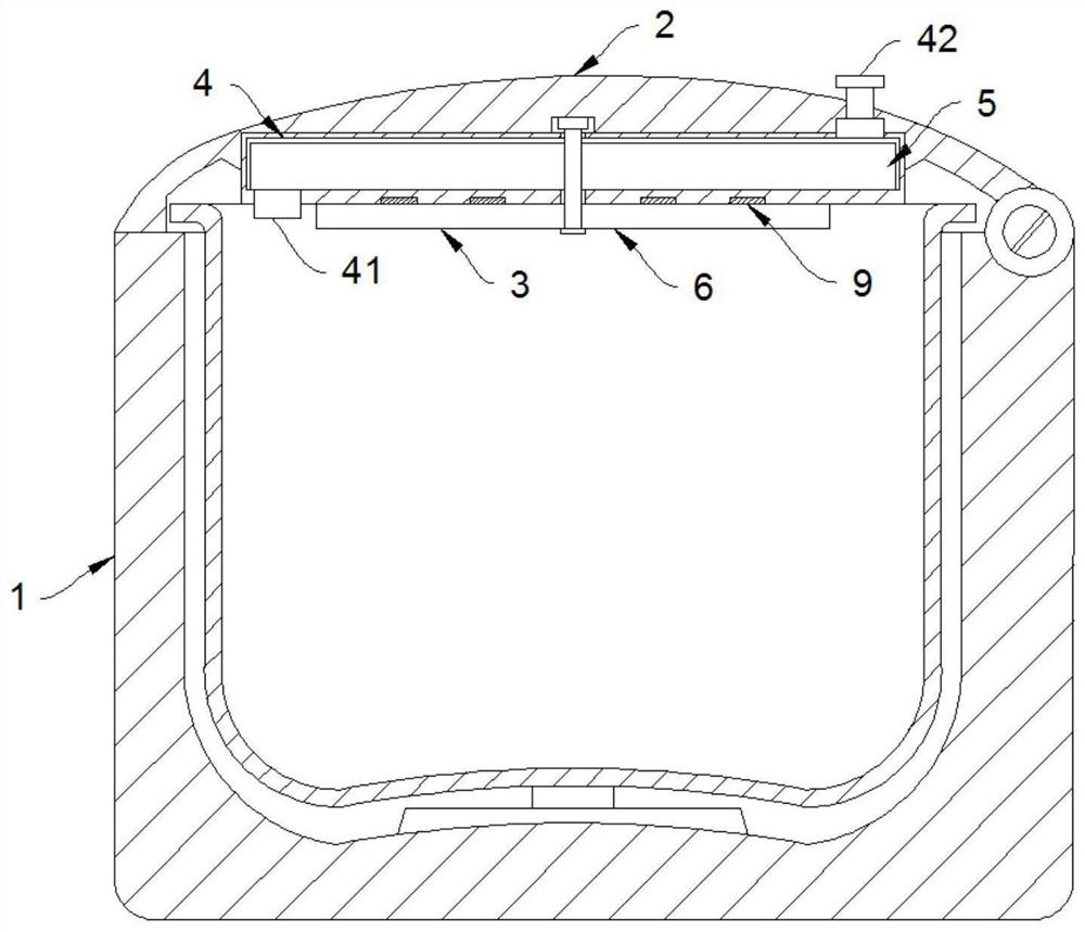
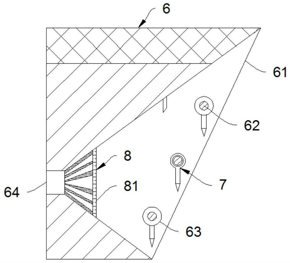
[0028] Such as Figure 1-2 As shown, a clean-type anti-overflow electric rice cooker includes a cooker body 1 and a cover body 2, the cooker body 1 and the cover body 2 are rotatably connected, the cover body 2 is provided with a cleaning device 3, and the cleaning device 3 includes a hot air chamber 4 and an air fan 5 And cleaning plate 6, it should be noted that the hot gas chamber 4 adopts a cylindrical structure, the fan blade of the air fan 5 adopts a rectangular structure, the length dimension of the fan blade is slightly smaller than the radius dimension of the hot gas chamber 4, and the height dimension of the fan blade is slightly smaller than The height dimension of the hot gas chamber 4 makes the fan blades can make good use of the hot gas in the pot body 1 to rotate.

[0029] Further, the end of the hot gas chamber 4 close to the pot body 1 is provided with an air inlet 41, and the end of the hot gas chamber 4 away from the pot body 1 is provided with an air outlet...

Embodiment 2

[0037] Such as image 3 Shown, the difference between this embodiment and embodiment 1 is:

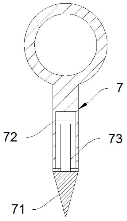
[0038]In order to prevent the defoaming needle 7 from rotating and defoaming, a small amount of air bubbles may adhere to the defoaming needle 7 and reduce the defoaming efficiency of the defoaming needle 7. The defoaming needle 7 is divided into needles 71 and the needle body 72. Only the needle head 71 is made of ferromagnetic material. The needle body 72 is provided with a sliding groove. plate, to prevent the needle head 71 from falling off during the rotation process, the needle head 71 and the magnetic block 9 are arranged in cooperation, so that when the defoaming needle 7 moves to the bottom of the magnetic block 9 under the drive of the cleaning plate 6, the needle head 71 of the defoaming needle 7 is on the magnetic block Under the attraction of 9, it rotates and rises. When the defoaming needle 7 is away from the bottom of the magnetic block 9, the needle head 71 swings und...


PUM


Abstract

The invention belongs to the field of kitchen appliances, in particular to a clean anti-overflow electric rice cooker, comprising a cooker body and a cover body, the cooker body and the cover body are rotatably connected, the cover body is provided with a cleaning device, and the cleaning device includes a hot air chamber, air fan and cleaning plate, the hot air chamber is fixedly connected to the cover body, the air fan is rotatably connected to the hot air chamber, the cleaning plate is coaxially fixedly connected to the air fan, the cleaning plate is rotatably connected to a defoaming needle, The defoaming needle is arranged in cooperation with the hot air chamber. The invention is simple in structure and easy to operate. By setting up a clean electric rice cooker, the electric rice cooker can clean the top cover by itself during the working process, and at the same time has a synchronous defoaming function, which can effectively prevent rice soup from overflowing during the use of the electric rice cooker. Improves the cleanliness of the unit.

Description

technical field [0001] The invention belongs to the field of kitchen appliances, in particular to a clean anti-overflow electric rice cooker. Background technique [0002] Electric rice cooker, also known as electric cooker and electric rice cooker, is a cooking utensil that uses electric energy to convert heat energy. It has the function of heating food and is easy to use, safe and reliable. It is one of the common kitchen equipment for household appliances. With the rapid development, people's functional requirements for various electrical appliances in life are also constantly improving, and the deficiencies of rice cookers are becoming more and more obvious. A solution is urgently needed to improve these deficiencies. [0003] In the prior art, most common rice cookers on the market use a steam valve structure to remove the steam inside the rice cooker during use. It is very easy to overflow rice soup, food debris, etc., which reduces the cooking efficiency of the rice ...

Claims


Application Information

Patent Timeline
Patent Type & Authority Patents(China)
IPC IPC(8): A47J27/56A47J36/00
CPCA47J27/56A47J36/00
Inventor 周小孟于国飞
Owner 王冬芳
Learn More