Anti-theft floor lock of roller shutter door

A technology for floor locks and rolling doors, applied in the field of anti-pry locks, which can solve problems such as easy failures and poor anti-pry performance, and achieve the effects of avoiding misoperation, enhancing safety, and excellent anti-pry performance

Pending Publication Date: 2020-07-10
南宁市天道锁具科技有限公司
View PDF1 Cites 4 Cited by
  • Summary
  • Abstract
  • Description
  • Claims
  • Application Information

AI Technical Summary

Problems solved by technology

However, this patent uses a single hook for locking, which is prone to failure...

Method used


Image

  • Anti-theft floor lock of roller shutter door
  • Anti-theft floor lock of roller shutter door
  • Anti-theft floor lock of roller shutter door

Examples


Embodiment 1

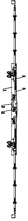
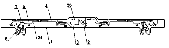
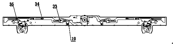
[0041] like Figure 1-4 As shown, the rolling door anti-theft floor lock of the present invention includes a lock body 1, a lock core 2, a tension spring 7, a travel transmission mechanism, a locking mechanism and an anti-callback mechanism 19; the lock core 2 is arranged in the middle of the lock body 1, The stroke transmission mechanism includes a lock bar 3, a first transmission lock bar 4 and a second transmission lock bar 5, and the lock bar 3 includes an upper tooth lock bar and a lower tooth lock bar, and the upper tooth lock bar and the lower tooth lock bar respectively It is arranged on the upper and lower parts of the lock core 2 and meshes with the gear of the lock core 2. The lock bar 3 is connected to one end of the first transmission lock bar 4, and the second drive lock bar 5 is connected to the other end of the first drive lock bar 4. One end is connected, and the anti-callback mechanism 19 is arranged on one side of the joint between the lock bar 3 and the fir...


PUM


Abstract

The invention discloses an anti-theft floor lock for a roller shutter door. The anti-theft floor lock is characterized by comprising a lock body, a lock cylinder, a tension spring, a stroke transmission mechanism, a locking mechanism and an anti-pull-back mechanism, wherein the lock cylinder is arranged in the middle of the lock body; the stroke transmission mechanism comprises a lock rod, a firsttransmission lock rod and a second transmission lock rod, wherein the lock rod comprises an upper tooth lock rod and a lower tooth lock rod, and the upper tooth lock rod and the lower tooth lock rodare arranged on the upper portion and the lower portion of the lock cylinder respectively and meshed with a lock cylinder gear; and the lock rod is connected with one end of the first transmission lock rod, the second transmission lock rod is connected with the other end of the first transmission lock rod, and the anti-pull-back mechanism is arranged on one side of the joint of the lock rod and the first transmission lock rod. The anti-theft floor lock for the roller shutter door is high in applicability, excellent in prying resistance, convenient to use, low in failure rate and convenient todisassemble, assemble and maintain.

Description

technical field [0001] The invention relates to the technical field of anti-picking locks, in particular to an anti-theft floor lock specially used for rolling shutter doors. Background technique [0002] The rolling gate, also known as the "rolling shutter door", is a door that is connected in series or in other combinations with a lot of movable joints. In a fixed slideway, the upper and lower doors are rotated around the scroll above the door. Rolling gates are suitable for commercial facades, garages, shopping malls, hospitals, factories and mines and other public places or residences. The rolling gate, especially the large door opening, can be opened conveniently and quickly in places where it is inconvenient to install the ground door body. For example, it is used for garage doors, shopping malls, fireproof rolling gates, and hangar doors. [0003] Currently commercially available electric rolling gates do not have a locking device, and utilize a motor as a drive swi...

Claims


Application Information

Patent Timeline
IPC IPC(8): E06B9/80E05B65/00E05B17/20E05B17/22E05C9/04E05C9/12E05C9/18E05B63/14
CPCE05B17/2003E05B17/22E05B63/146E05B65/0021E05C9/041E05C9/047E05C9/1858E06B9/80E06B2009/801
Inventor 覃文东
Owner 南宁市天道锁具科技有限公司
Why Eureka
Try Eureka