Emergency release coupler

A technology of breakaway valves and valve bodies, which is applied in the direction of safety valves, balance valves, valve devices, etc., which can solve the problems of easy fatigue fracture and disconnection of breakaway valves, and achieve the effect of avoiding fatigue fractures

Pending Publication Date: 2020-07-10
GILBARCO CHINA
View PDF0 Cites 1 Cited by
  • Summary
  • Abstract
  • Description
  • Claims
  • Application Information

AI Technical Summary

Problems solved by technology

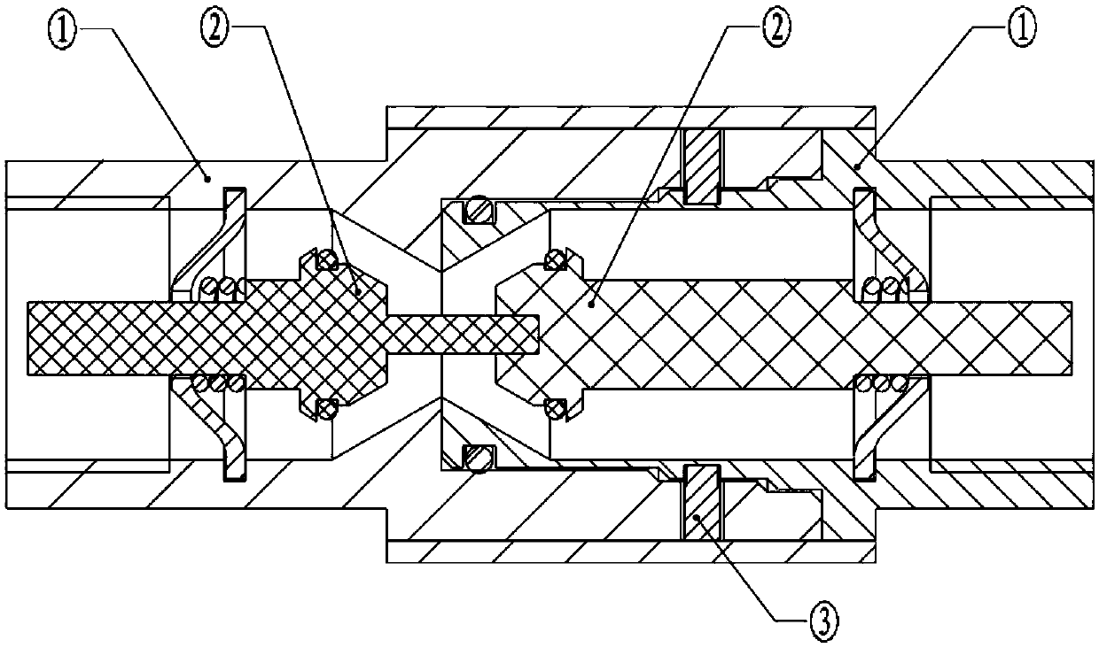
[0004] However, during use, due to the long-term impact of the pin ③, the pin ③ is subjected to short-term tensile impacts during the frequent start and stop of the hydraulic system, and the rubber hose is pulled during refueling operations, and is prone to fatigue and fracture, causing the breakaway valve to be broken in the non-standard position. Disconnect under vehicle pulling conditions

Method used


Image

  • Emergency release coupler
  • Emergency release coupler
  • Emergency release coupler

Examples


Embodiment Construction

[0027] In order to make the purpose, technical solutions and advantages of the embodiments of the present invention clearer, the technical solutions in the embodiments of the present invention will be clearly and completely described below in conjunction with the drawings in the embodiments of the present invention. Obviously, the described embodiments It is a part of embodiments of the present invention, but not all embodiments. Based on the embodiments of the present invention, all other embodiments obtained by persons of ordinary skill in the art without making creative efforts belong to the protection scope of the present invention.

[0028] In the following detailed description, reference is made to the accompanying drawings which are included in the specification and which illustrate specific embodiments of the application and which are included in this application. In the drawings, like reference numerals describe substantially similar components in different views. Va...


PUM


Abstract

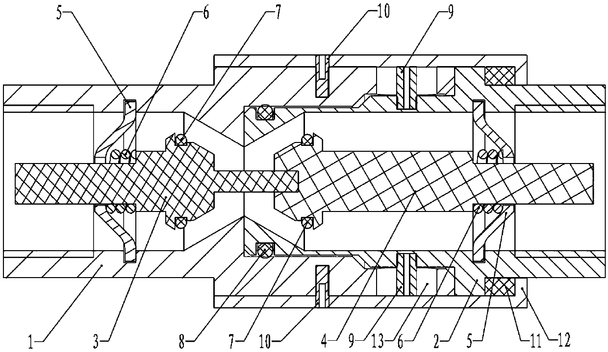
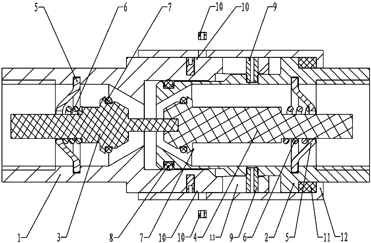
The invention relates to a valve, in particular to an emergency release coupler. The emergency release coupler comprises a first valve body, a second valve body connected with the first valve body, ahousing outside the first valve body and the second valve body, a first emergency release member for limiting relative movement of the housing and the first valve body, and a second emergency releasemember for limiting relative movement of the first valve body and the second valve body. In the axial direction of the first valve body, a first gap between the first emergency release member and thehousing is smaller than a second gap between the second emergency release member and the first valve body. Due to the fact that the first emergency release member bears tensile force before the secondemergency release member, when a rubber pipe is impacted by short-time tensile force in the process that a hydraulic system is frequently started and stopped or the rubber pipe is pulled in the oiling operation, the first emergency release member firstly absorbs the tensile force impact and plays a buffering role, and fatigue fracture of the second emergency release member is avoided.

Description

technical field [0001] The invention relates to a valve, in particular to a breakaway valve. Background technique [0002] In the fuel tanker industry used in gas stations, in order to avoid problems such as a large amount of fuel leakage caused by the fuel gun being inserted into the fuel tank when the vehicle is started, the vehicle pulls the fuel tanker, and the oil delivery pipe between the fuel gun and the tanker body is usually Install the breakaway valve. [0003] figure 1 is a structural schematic diagram of a breakaway valve in the related art, such as figure 1 As shown, the breakaway valve includes two valve bodies ①, two valve cores ② and pins ③ fixing the two valve bodies ①. When the pull-off valve is subjected to a tension exceeding its setting, the pin breaks, and the two valve bodies ① will be automatically disconnected, one end stays at the end of the oil gun, and the other end stays at the end of the fuel dispenser body, and the two valve cores ② separate...

Claims


Application Information

Patent Timeline
Patent Type & Authority Applications(China)
IPC IPC(8): F16K17/40
CPCF16K17/403F16K17/406
Inventor 高庆轩江淮陈文虎刘旻
Owner GILBARCO CHINA
Why Eureka
Try Eureka