

Refrigeration container defrosting system and defrosting method
A refrigerated container and control system technology, applied in defrosting, household refrigeration equipment, cooling fluid circulation equipment, etc., can solve the problem of high energy consumption of defrosting, achieve low energy consumption of defrosting, fast defrosting speed, and fan displacement big effect
- Summary
- Abstract
- Description
- Claims
- Application Information
AI Technical Summary
Problems solved by technology
Method used
Image

Examples
Embodiment 1
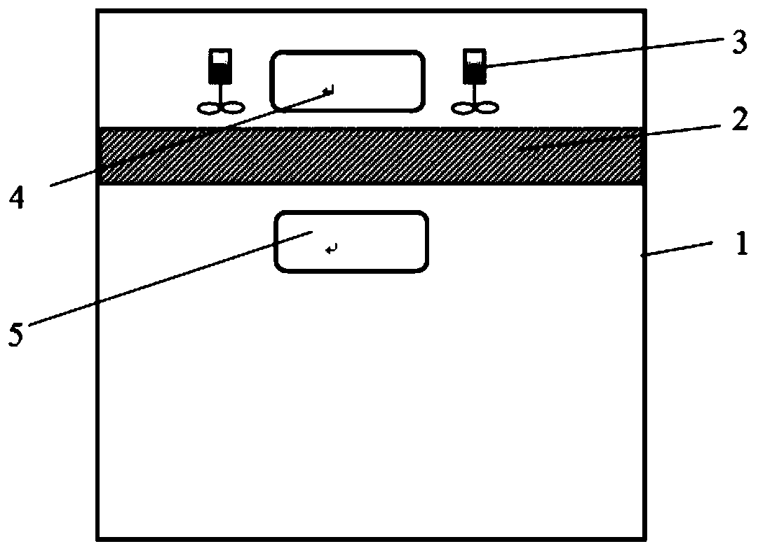
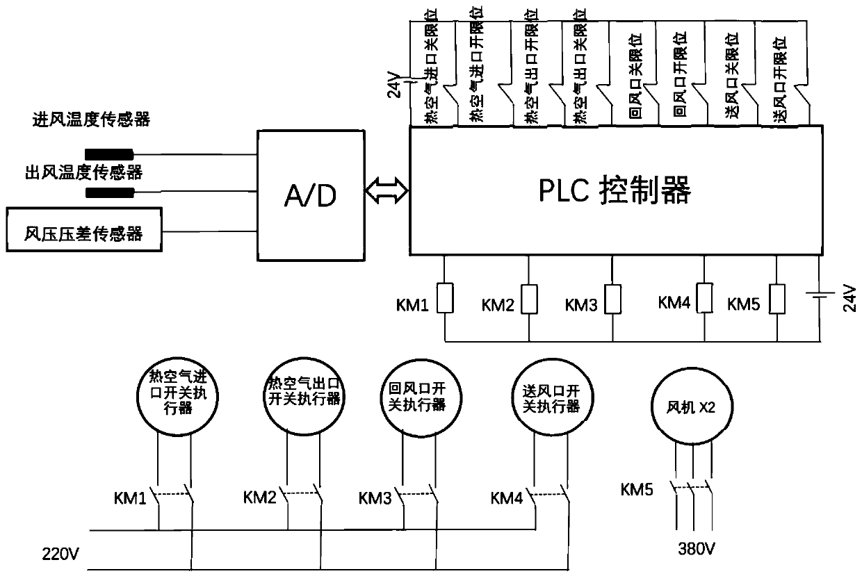
[0055] The refrigerated container defrosting system includes a box body 1, an evaporator 2, a hot air inlet 4, a hot air outlet 5, an air supply port 6 in the box, an air return port 7 in the box, a control system, and a switch actuator. The evaporator 2 is set in A fan 3 is arranged on the inner wall of the top of the box body 1 and at the evaporator 2, and the hot air inlet 4 and the hot air outlet 5 are respectively arranged on the upper part and the lower part of the rear wall of the box body 1 and are respectively located on both sides of the evaporator 2, The air return port 7 in the box and the air supply port 6 in the box are respectively arranged on the upper part and the lower part of the front wall of the box body 1 and are respectively located on both sides of the evaporator 2. The switch actuator is used to control the hot air inlet 4, the hot air The opening and closing of the outlet 5, the air supply port 6 in the box and the air return port 7 in the box, the con...
Embodiment 2
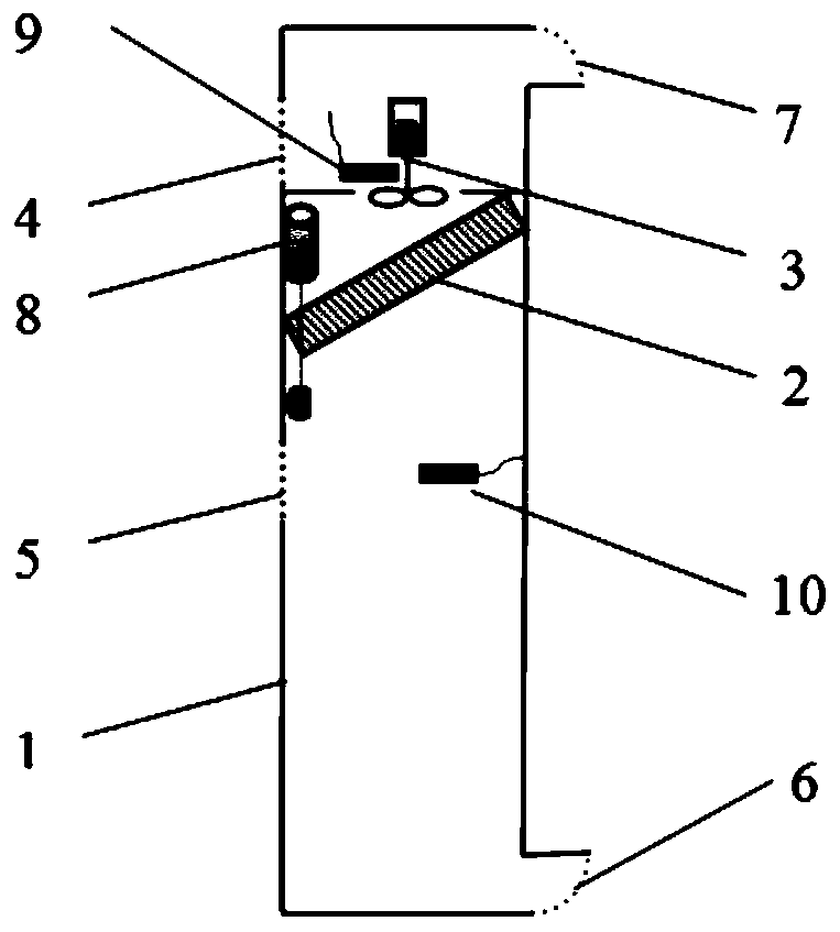
[0058] The defrosting system for refrigerated containers includes box body 1, evaporator 2, hot air inlet 4, hot air outlet 5, air supply port 6 in the box, air return port 7 in the box, air inlet temperature sensor 9, air outlet temperature sensor 10, and control system And the switch actuator, the evaporator 2 is arranged on the inner wall of the top of the box body 1 and the fan 3 is arranged at the evaporator 2, and the hot air inlet 4 and the hot air outlet 5 are respectively arranged on the upper part of the rear wall of the box body 1 and the lower part and are respectively located on both sides of the evaporator 2, the air return port 7 in the box and the air supply port 6 in the box are respectively arranged on the upper part and the lower part of the front wall of the box body 1 and are respectively located on both sides of the evaporator 2, the switch The actuator is used to control the opening and closing of the hot air inlet 4, the hot air outlet 5, the air supply ...
Embodiment 3
[0067] The defrosting system for a refrigerated container includes a box body 1, an evaporator 2, a hot air inlet 4, a hot air outlet 5, an air supply port 6 in the box, an air return port 7 in the box, a differential pressure sensor 8, a control system, and a switch actuator. The evaporator 2 is arranged on the inner wall of the top of the box body 1 and the evaporator 2 is provided with a fan 3, and the hot air inlet 4 and the hot air outlet 5 are respectively arranged on the upper part and the lower part of the rear wall of the box body 1 and are respectively located in the evaporator 2, the air return port 7 in the box and the air supply port 6 in the box are respectively arranged on the upper part and the lower part of the front wall of the box body 1 and are respectively located on both sides of the evaporator 2, and the switching actuator is used to control the hot air The opening and closing of the inlet 4, the hot air outlet 5, the air supply port 6 in the box and the ...
PUM
 Abstract
Description
Claims
Application Information