Supercharge Your Innovation With Domain-Expert AI Agents!

Electric mosquito swatter with induction type child lock

An electric mosquito swatter and induction technology are applied in the field of electric mosquito swatters with induction child locks, which can solve the problems of impact, leakage hazards, and single triggering method of electric mosquito swatters.

Inactive Publication Date: 2020-07-17
UNIV OF ELECTRONICS SCI & TECH OF CHINA ZHONGSHAN INST
View PDF6 Cites 0 Cited by
  • Summary
  • Abstract
  • Description
  • Claims
  • Application Information

AI Technical Summary

Problems solved by technology

[0002] Because most of the electric mosquito swatters on the market adopt a single start-up trigger method, which does not have good safety performance, and because unscrupulous merchants control production costs, there are many product defects, and the quality of quality control cannot be guaranteed, which will lead to the following disadvantages: 1. A single switch or button is often used to trigger the electric mosquito swatter. When people, especially children, pregnant women or the elderly use the electric mosquito swatter, it may cause accidental contact and cause electric shock; 2. Although the current of the electric mosquito swatter is small, the instantaneous voltage is as high as Thousand volts, without a reliable self-locking link may cause leakage and cause harm; 3. It will cause physical or even mental impact on the person who is electrocuted; 4. Because the existing electric mosquito swatter has a single trigger method and uses It lacks convenience and increases the difficulty of use

Method used


Image

  • Electric mosquito swatter with induction type child lock
  • Electric mosquito swatter with induction type child lock
  • Electric mosquito swatter with induction type child lock

Examples


Embodiment Construction

[0019] The following will clearly and completely describe the technical solutions in the embodiments of the present invention in conjunction with the accompanying drawings in the embodiments of the present invention; obviously, the described embodiments are only part of the embodiments of the present invention, not all embodiments, based on The embodiments of the present invention and all other embodiments obtained by persons of ordinary skill in the art without making creative efforts belong to the protection scope of the present invention.

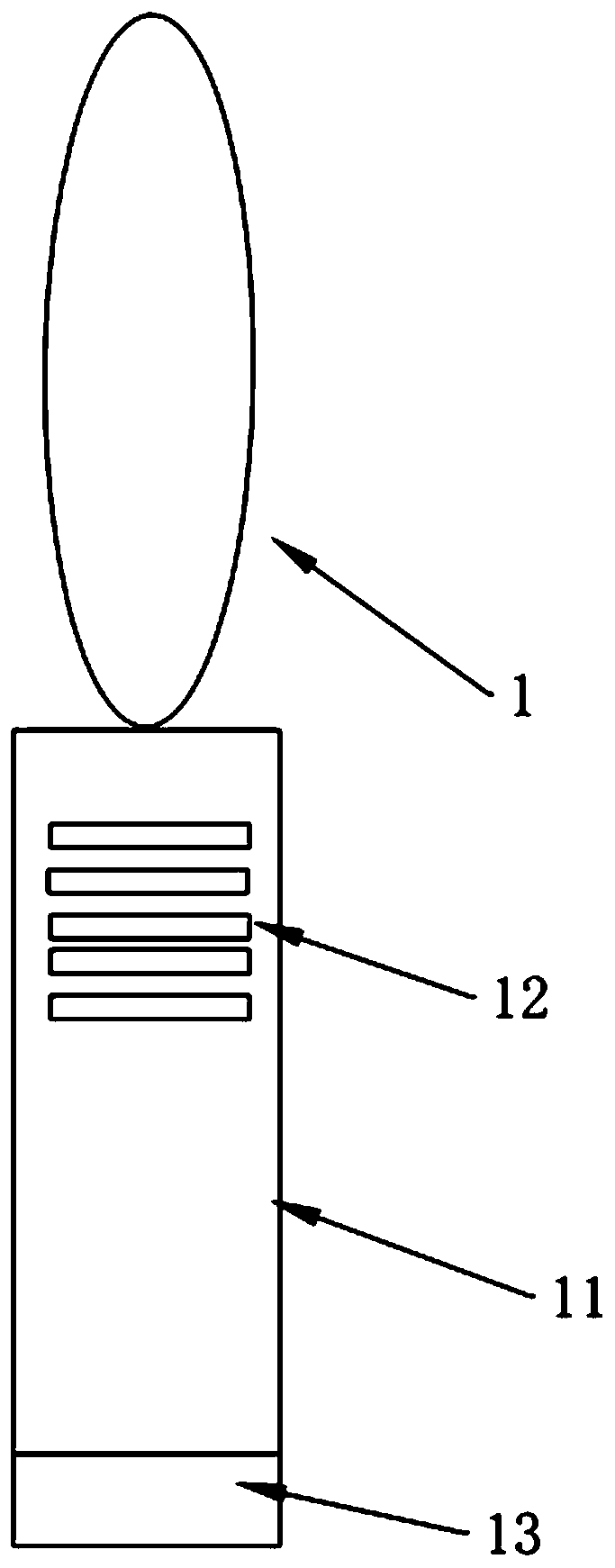
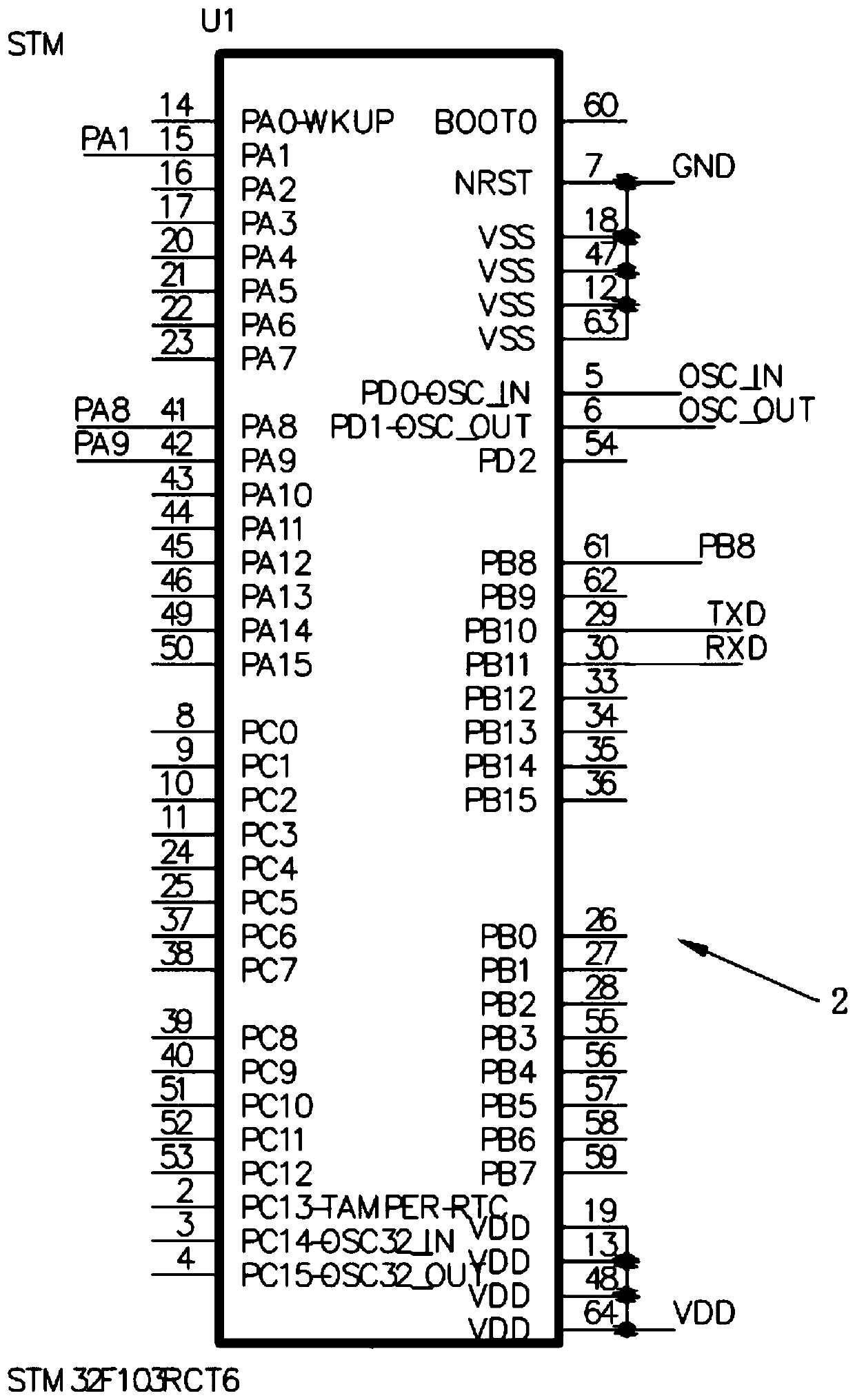
[0020] see Figure 1 to Figure 6 , an electric mosquito swatter with an inductive child lock, comprising an electric mosquito swatter body 1, the electric mosquito swatter body 1 has a racket rod 11 for holding, and a first touch sensor is arranged above the racket rod 11 12. A second touch sensor 13 is set under the racket rod 11. The main control module 2 and the main circuit module for realizing the normal operation of the electric mo...


PUM


Abstract

The invention discloses an electric mosquito swatter with an induction type child lock. The electric mosquito swatter with the induction type child lock comprises an electric mosquito swatter body; the electric mosquito swatter body has a racket rod used for being held by a hand; a first touch sensor is arranged at the upper part of the racket rod; a second touch sensor is arranged at the lower part of the racket rod; a main control module and a main circuit module are arranged in the electric mosquito swatter body; the main circuit module realizes normal working of the electric mosquito swatter body; both the first touch sensor and the second touch sensor are electrically connected with the input end of the main control module; the output end of the main control module is electrically connected with the main circuit module; children have small hands; in a condition that the electric mosquito swatter is held by one hand, the product cannot be electrified due to the fact that the firsttouch sensor and the second touch sensor cannot be contacted at the same time; therefore, while touching the electric mosquito swatter body, the other hand also cannot be electrified; the first touchsensor and the second touch sensor can be contacted at the same time only when the electric mosquito swatter is held by two hands at the same time; the electric mosquito swatter body can be electrified; but, the small hands cannot be electrified; and simultaneously, mosquitoes can be killed.

Description

technical field [0001] The invention relates to the technical field of electric mosquito swatters, in particular to an electric mosquito swatter with an inductive child lock. Background technique [0002] Because most of the electric mosquito swatters on the market adopt a single start-up trigger method, which does not have good safety performance, and because unscrupulous merchants control production costs, there are many product defects, and the quality of quality control cannot be guaranteed, which will lead to the following disadvantages: 1. A single switch or button is often used to trigger the electric mosquito swatter. When people, especially children, pregnant women or the elderly use the electric mosquito swatter, it may cause accidental contact and cause electric shock; 2. Although the current of the electric mosquito swatter is small, the instantaneous voltage is as high as Thousand volts, without a reliable self-locking link may cause leakage and cause harm; 3. I...

Claims


Application Information

Patent Timeline
IPC IPC(8): A01M3/02
CPCA01M3/025
Inventor 吴佳楠邓子良梁智峰温文基彭亿姿刘金华
Owner UNIV OF ELECTRONICS SCI & TECH OF CHINA ZHONGSHAN INST
Features
  • R&D
  • Intellectual Property
  • Life Sciences
  • Materials
  • Tech Scout
  • Unparalleled Data Quality
  • Higher Quality Content
  • 60% Fewer Hallucinations
Learn More