

Back pounding auxiliary device
A technology of an auxiliary device and a back bar, which is used in massage auxiliary products, instruments for compressing reflex points, physical therapy, etc., can solve problems such as inability to complete, inability to adapt to different users, uncontrollable force, etc., and achieve good practicability. , the effect of expanding the scope of action
- Summary
- Abstract
- Description
- Claims
- Application Information
AI Technical Summary
Problems solved by technology
Method used
Image

Examples
Embodiment 1
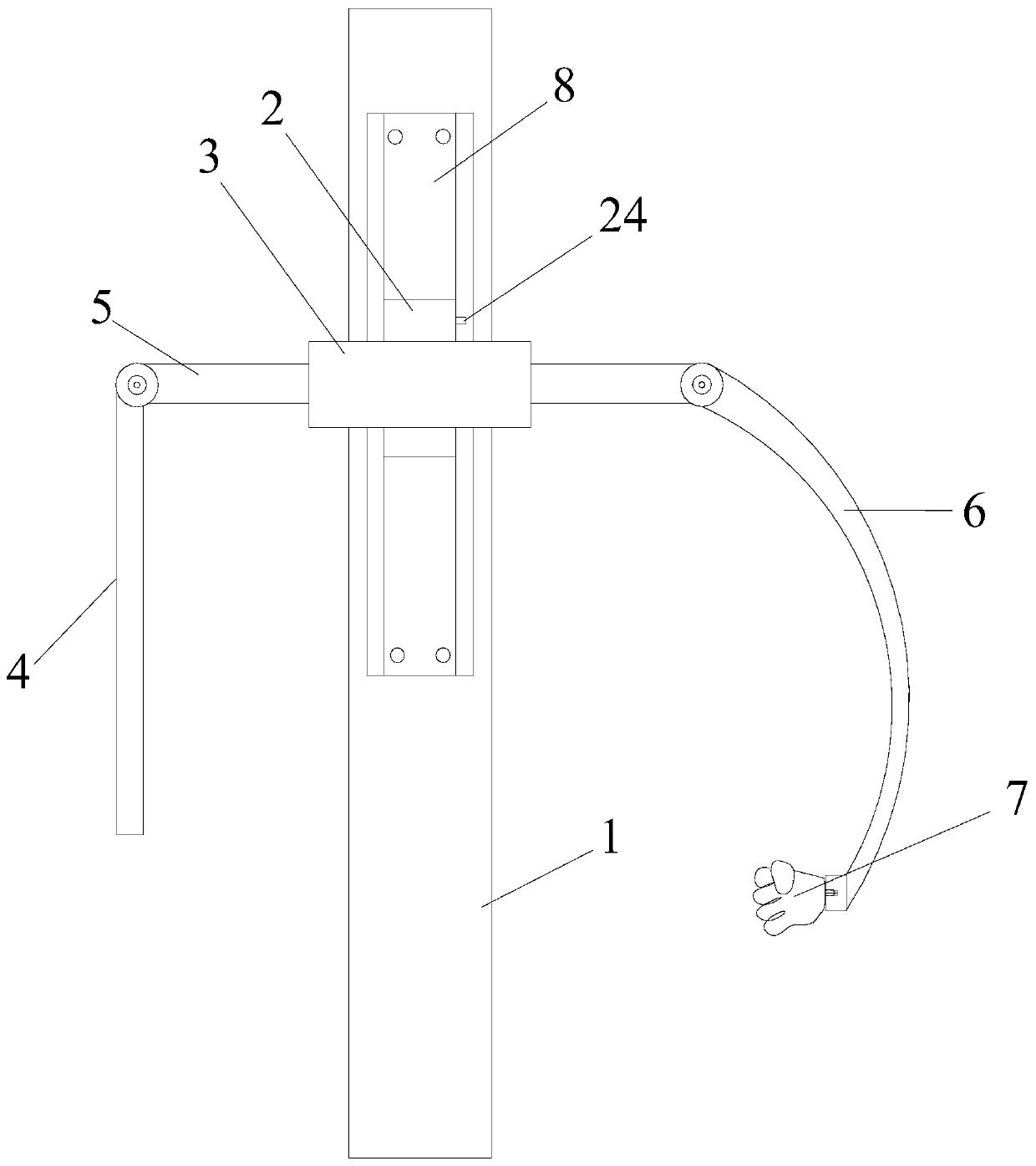
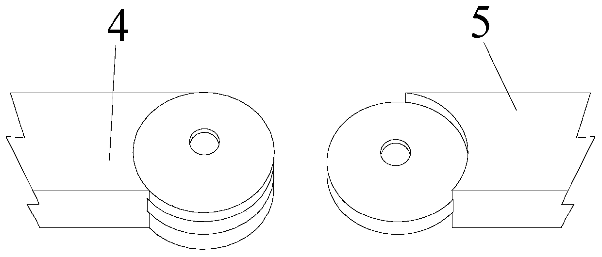
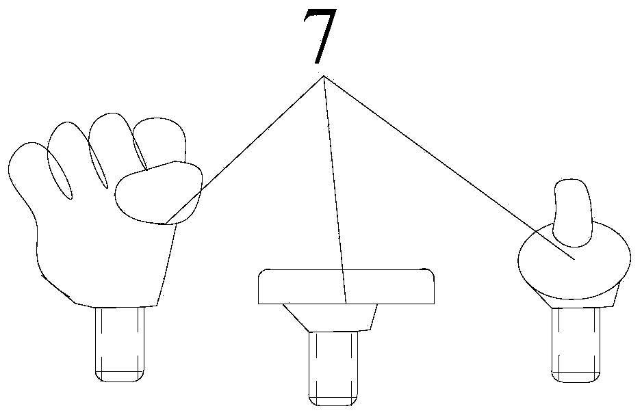
[0038] figure 1 It is a structural schematic diagram of the back-beating auxiliary device in Embodiment 1 of the present invention, as figure 1 As shown, a back-beating auxiliary device disclosed in the embodiment of the present invention is characterized in that it includes a support frame 1, a slider 2, an outer sleeve 3, a push-pull rod 4, a connecting rod 5, a back-beating rod 6 and a profiling part 7. The support frame 1 is strip-shaped, the direction of the long side of the support frame 1 is its length direction, and the direction perpendicular to the length direction of the support frame 1 is its width direction. The positioning slots 8 are arranged along the length direction of the support frame 1 , and when the support frame 1 is thick, the position limiting slots 8 are obtained by removing material from the support frame 1 . The slider 2 is slidably arranged in the limiting groove 8 along the length direction of the support frame 1, and the cross section of the sli...
Embodiment 2
[0043] Figure 4 It is a structural schematic diagram of the back-beating auxiliary device in Embodiment 2 of the present invention, as Figure 4 As shown, as another embodiment of the present invention, different from the previous embodiment, the backbeating auxiliary device also includes a linkage rod 15, an inner sleeve 16 and a resistance screw 17, and the connecting rod 5 is fixedly arranged on the inner sleeve 16. Inside, the linkage rod 15 is slidably arranged in the inner sleeve 16, one end of the linkage rod 15 is hinged to the part of the push-pull rod 4 located on one side of the connection rod 5, and the other end of the linkage rod 15 is hinged to the part of the backbeating rod 6 located on the other side of the connection rod 5. The side part, specifically, in this embodiment, one end of the linkage rod 15 is hinged to the push-pull rod 4 on the side of the connecting rod 5 facing the profiling portion 7, and the other end of the linkage rod 15 is hinged to the ...
Embodiment 3
[0047] Figure 5 It is a structural schematic diagram of the back-beating auxiliary device in Embodiment 3 of the present invention, as Figure 4 As shown, as another embodiment of the present invention, different from the previous embodiment, in this embodiment, the part of the backbeating rod 6 located on the side of the connecting rod 5 away from the profiling part 7 is not provided with a protruding part. Instead, the two ends of the linkage rod 15 are connected with the push-pull rod 4 and the back-beating rod 6 respectively by two disc buckles 18 . Figure 10 It is a structural schematic diagram of the dish-shaped ring buckle in Embodiment 3 of the present invention, such as Figure 10 As shown, the disc buckle 18 includes a butterfly piece 19 and two hinge parts 20 , and the two hinge parts 20 are arranged on opposite sides of the butterfly piece 19 .
[0048] Specifically, one disc-shaped ring buckle 18 is fixedly connected to one end of the connecting rod 5, and the...
PUM
 Abstract
Description
Claims
Application Information