Curved glass flexible shaft bending tempering forming method

A technology of curved glass and molding method, which is applied in the direction of glass tempering, glass molding, glass remolding, etc., can solve the problems of difficult molding of glass edges, etc., and achieve the effect that is beneficial to production efficiency

Active Publication Date: 2020-07-17
LUOYANG LANDGLASS TECH CO LTD
View PDF8 Cites 2 Cited by
  • Summary
  • Abstract
  • Description
  • Claims
  • Application Information

AI Technical Summary

Problems solved by technology

[0003] The purpose of the present invention is to provide a method for bending and tempering curved glass flexible shafts, so as to eliminate the above-mentioned transition point and the phenomenon of glass vacating, and further solve the technical problem that the edge of the glass is difficult to form

Method used


Image

  • Curved glass flexible shaft bending tempering forming method
  • Curved glass flexible shaft bending tempering forming method
  • Curved glass flexible shaft bending tempering forming method

Examples


Embodiment 1

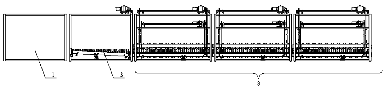
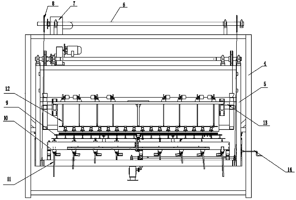
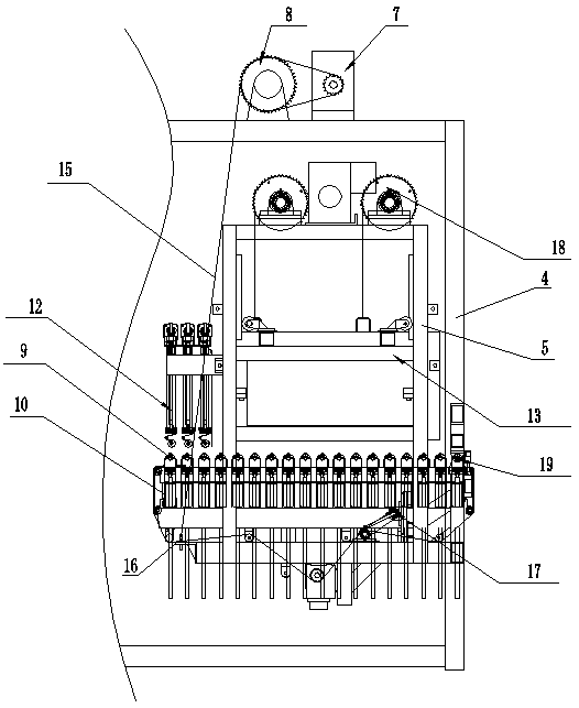
[0046] Embodiment 1: as figure 2 , 3 As shown, the transition section 2 includes a main frame 4 and a sub-frame 5, and a plurality of aluminum profile square tubes 10 are fixedly arranged at intervals along the glass conveying direction on the sub frame 5, and each aluminum profile square tube 10 is correspondingly arranged A flexible shaft roller table 9 parallel to it, and the corresponding gradual arc mechanism 11 realizes the bending of the flexible shaft roller table 9 into an arc, and the roller table surface formed by multiple flexible shaft roller tables 9 in a straight line state It is coplanar with the inner roller surface of the heating furnace 1; the end of the sub-frame 5 close to the heating furnace 1 is rotatably connected with the main frame 4 in a hinged manner, and its rotation axis and the first flexible shaft roller in a straight state The central axis of the road 9 is collinear and parallel to the ceramic roller table 25 of the heating furnace 1, and the...

Embodiment 2

[0057] Embodiment 2: In this embodiment, the arrangement of the flexible shaft roller table 9 and the gradual arc-changing mechanism 11 is different from that of Embodiment 1, and the rest of the structure is the same.

[0058] In this embodiment, the aluminum profile square tubes 10 are arranged on the sub-frame 5 at intervals along the direction perpendicular to the glass conveying direction, the length direction of the aluminum profile square tubes 10 is consistent with the glass conveying direction, and the flexible shaft roller table 9 is perpendicular to the aluminum profile square tube 10 are set, and each flexible shaft roller table 9 is rotatably installed on a plurality of aluminum profile square tubes 10 through the roller table seat.

[0059] The gradual arcing mechanism 11 adopts a chain plate structure 22 commonly used in the field, which can also be called a tooth plate structure. The chain plate structure 22 can be provided with two groups, which are respectivel...


PUM


Abstract

The invention discloses a curved glass flexible shaft bending tempering forming method. When in production of the curved glass, after the glass is discharged from a heating furnace, the glass is preformed in the trend that the two side parts in the transverse direction are kept on the same plane and the middle part in the transverse direction gradually sinks along the conveying direction, then enters a forming and toughening section under the condition that the two side parts in the transverse direction are supported, and is finally formed and toughened to finish the bending and toughening manufacturing of the curved glass. After the method is adopted, when the glass gradually becomes arc and enters the forming tempering section, the flexible shaft roller ways are always arranged at the two side parts of the glass in the transverse direction to be used as supports, and the edge parts are not suspended, so that the wave bending phenomenon of the edge parts is eliminated.

Description

technical field [0001] The invention belongs to the technical field of glass tempering, and in particular relates to a bending and tempering forming method of a curved glass flexible shaft. Background technique [0002] At present, when producing ultra-long curved tempered glass (including double-curved and single-curved surfaces), due to the large glass layout, it must be completed by gradual molding. However, in the process of gradual forming, it is generally carried out in a way that the middle part is horizontal and the sides gradually change upwards, that is, when the flexible shaft roller table in the gradual change section starts arcing, the middle part does not move and remains horizontal, and the two ends gradually start arcing. In the forming and tempering section connected with the gradient section, the forming and tempering section needs to be lifted to make the roller table surface of the flexible shaft roller table and the middle part of the tapering section ro...

Claims


Application Information

Patent Timeline
IPC IPC(8): C03B23/025C03B27/044
CPCC03B23/025C03B27/044Y02P40/57C03B23/0254C03B27/0447C03B35/166C03B35/187C03B23/033C03B27/00
Inventor 赵雁朱有成崔笑尘石志勇
Owner LUOYANG LANDGLASS TECH CO LTD
Why Eureka
Try Eureka