Horizontal floor drain

A floor drain, horizontal row technology, applied in drainage structures, waterway systems, water supply devices, etc., can solve problems such as water leakage and excessive occupation, and achieve the effect of reducing costs, saving installation space, and reducing installation height.

Pending Publication Date: 2020-07-17
青岛海鸥福润达家居集成有限公司
View PDF0 Cites 1 Cited by
  • Summary
  • Abstract
  • Description
  • Claims
  • Application Information

AI Technical Summary

Problems solved by technology

[0002] At present, the common form of horizontal row body on the market will occupy too much dimension in the height direction in the case of horizontal drainage on the same layer. The horizontal row body adopts the production process of separate molding and processing. The horizontal row body is divided into two parts Parts are molded and processed separately, and then glued or ultrasonically welded, there is a potential risk of water leakage. To address these defects, it is necessary for us to design horizontal floor drains

Method used


Image

  • Horizontal floor drain
  • Horizontal floor drain
  • Horizontal floor drain

Examples


Embodiment Construction

[0014] The technical solutions of the present invention will be clearly and completely described below in conjunction with the embodiments. Apparently, the described embodiments are only some of the embodiments of the present invention, not all of them. Based on the embodiments of the present invention, all other embodiments obtained by persons of ordinary skill in the art without creative efforts fall within the protection scope of the present invention.

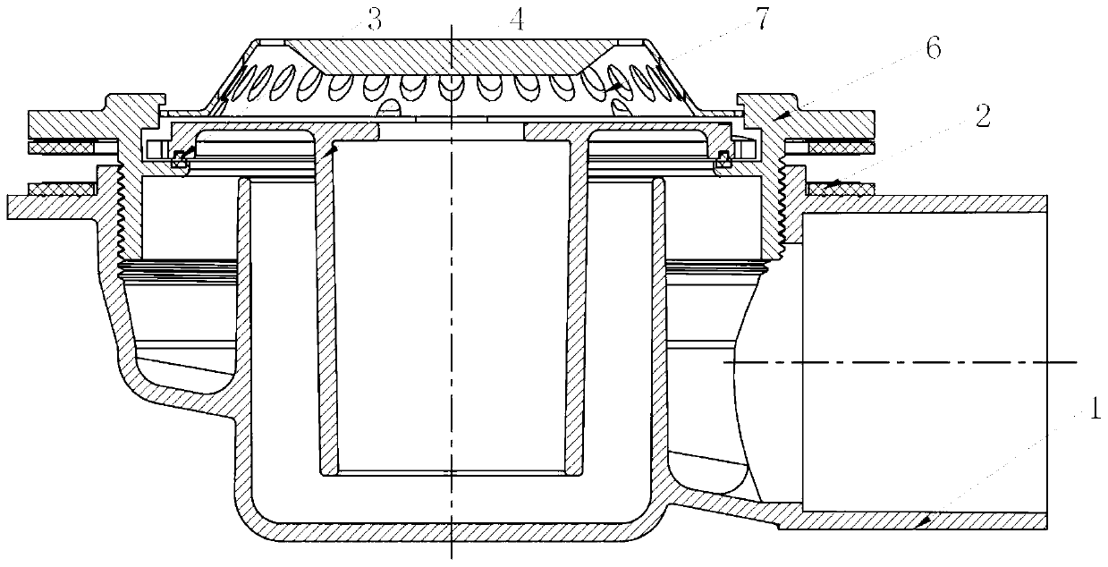
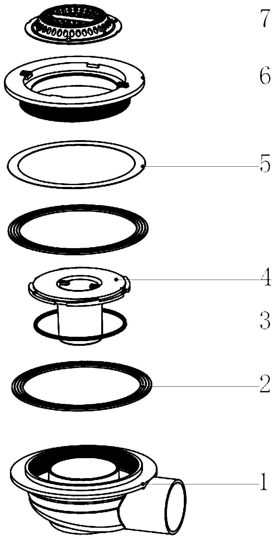
[0015] Such as Figure 1-4 As shown, the horizontal floor drain includes floor drain body 1, rubber pad a2, rubber pad b3, funnel 4, gasket 5, lock nut 6 and filter screen 7, floor drain body 1 is divided into an inner water seal cavity and an outer overflow cavity , the outer edge of the lower port of the lock nut 6 is threadedly connected with the inner edge of the overflow cavity of the floor drain body 1, the outer round top of the upper mouth of the floor drain body 1 and the outer round bottom of the upper mouth of th...


PUM


Abstract

The invention discloses a horizontal floor drain. The floor drain comprises a floor drain body, rubber pads a, a rubber pad b, a funnel, a gasket, a lock nut and a filter screen, wherein the floor drain body is divided into an inner water seal cavity and an outer overflow cavity, the outer edge of a lower end opening of the lock nut is in threaded connection with the inner edge of the outer overflow cavity of the floor drain body, the rubber pads a are arranged at the top of the outer circle of the upper opening of the floor drain body and the bottom of the outer circle of the upper opening ofthe lock nut correspondingly, the gasket is arranged between the bottom of the outer circle of the upper opening of the lock nut and the corresponding rubber pad a, the funnel vertically penetrates through a center hole of the lock nut to be inserted into the inner water seal cavity, the outer circle of the top of the funnel is in lap joint with the inner circle of the middle of the lock nut, theouter circle of the top of the funnel is connected with the inner circle of the middle of the lock nut through the rubber pad b, and the filter screen is placed at the top of the funnel. According tothe horizontal floor drain, the hidden danger of water leakage caused by bonding is effectively avoided, the requirement of installation height is effectively lowered, the number of parts is reduced,the cost is reduced, and the installation space is saved.

Description

technical field [0001] The invention relates to the technical field of sewer floor drain structures, in particular to horizontal floor drains. Background technique [0002] At present, the common form of horizontal row body on the market will occupy too much dimension in the height direction in the case of horizontal drainage on the same layer. The horizontal row body adopts the production process of separate molding and processing. The horizontal row body is divided into two parts Parts are molded separately, and then glued or ultrasonically welded, there is a potential risk of water leakage. To address these defects, it is necessary for us to design horizontal floor drains. Contents of the invention [0003] The purpose of the present invention is to provide horizontal floor drains, which effectively avoids the hidden danger of water leakage due to bonding, effectively reduces the requirements for installation height, reduces the number of parts, reduces costs, and saves...

Claims


Application Information

Patent Timeline
Patent Type & Authority Applications(China)
IPC IPC(8): E03F5/04E03F5/06
CPCE03F5/0407E03F5/06E03F5/041
Inventor 唐台英
Owner 青岛海鸥福润达家居集成有限公司
Why Eureka
Try Eureka