Check patentability & draft patents in minutes with Patsnap Eureka AI!

Spectacle lens and method for producing same

A technology of spectacle lenses and volumetric elements, applied in glasses/goggles, lenses, and other household appliances, etc., can solve problems such as restrictions, unsightly large edge thickness, and small design freedom

Pending Publication Date: 2020-07-24
CARL ZEISS VISION INT GMBH
View PDF24 Cites 0 Cited by
  • Summary
  • Abstract
  • Description
  • Claims
  • Application Information

AI Technical Summary

Problems solved by technology

[0018] 1. Large spatial separation between the near-vision area and the far-sighted area
[0019] 2. According to Mahmoud's theorem (Minkwitz's theorem), in the case of a smooth transition from the distance zone to the near zone in a zoom lens, astigmatic distortion towards the edge inevitably occurs
[0021] 4. In the case of non-progressive addition lenses, such as in the case of bifocal or trifocal lenses, a visible aesthetically unattractive fringe between the primary lens and the sub-elements
[0022] 5. Visibly unaesthetically large edge thickness in the case of spectacle lenses with strong refractive power; especially in the case of myopic people, high prism values ​​lead to thicker edges of spectacle lenses
[0023] 6. In the case of prescriptions for forms of spectacle lens front surfaces and / or spectacle frames that are considered aesthetically pleasing, limitations related to the producibility of corrective spectacles; Spectacle lenses are very constrained and thus result in correspondingly little design freedom
[0032] Although various methods are available to produce spectacle lenses that meet the aesthetic perception needs of many people, further improvements are still needed

Method used


Image

  • Spectacle lens and method for producing same
  • Spectacle lens and method for producing same
  • Spectacle lens and method for producing same

Examples


Embodiment Construction

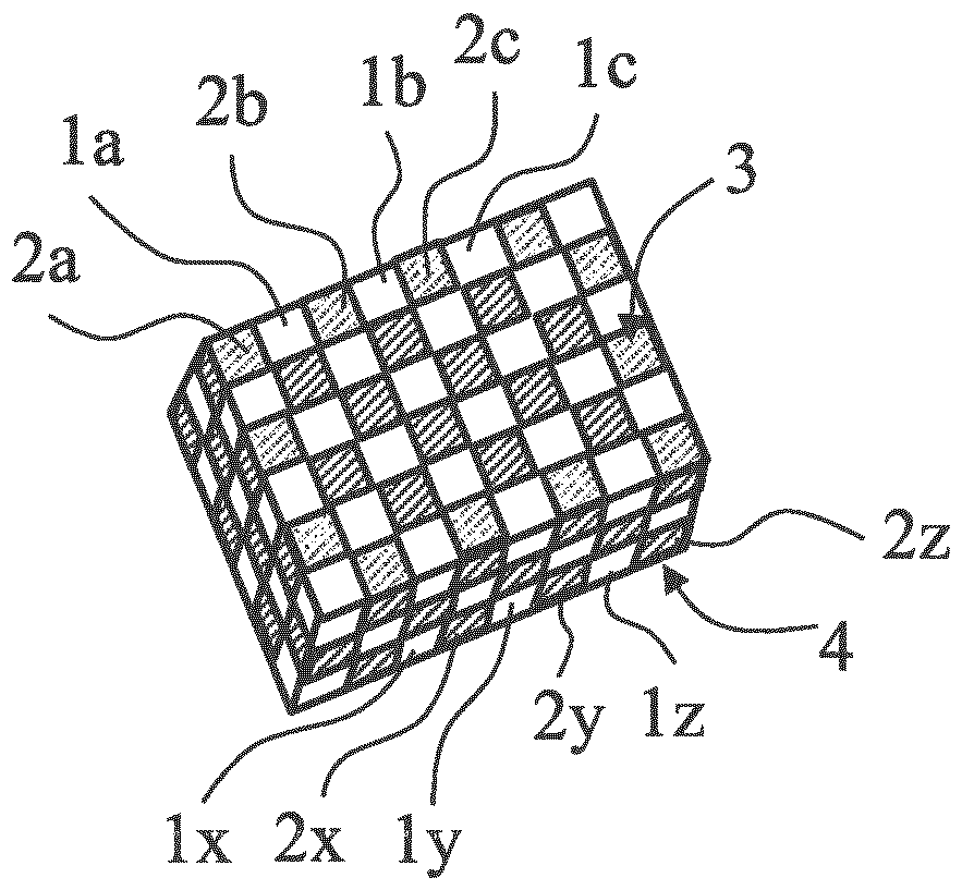
[0114] The explanation given above is that the spectacle lens according to the invention comprises at least two groups of volume elements. The two groups of volume elements (hereinafter referred to as first and second groups of volume elements) each comprise a plurality of corresponding volume elements. The volume elements of the first volume element group are hereinafter referred to as first volume elements; the volume elements of the second volume element group are hereinafter referred to as second volume elements.

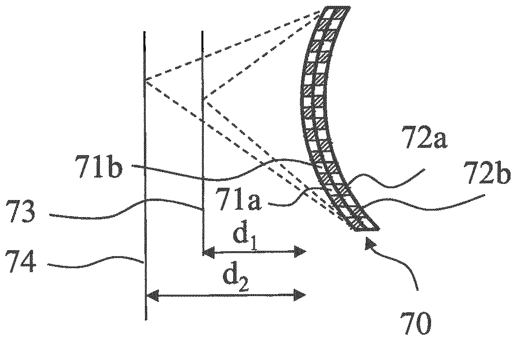
[0115] These first volume elements are arranged in the pattern of grid points of the geometric grid and form a first partial grid. The volume elements of the first group of volume elements together form the first part of the spectacle lens. Together they define the area of ​​the spectacle lens through which the spectacle wearer looks in the case of the intended use, said area having a refractive power for viewing the first object distance.

[0116] These secon...


PUM

PropertyMeasurementUnit
Abbe numberaaaaaaaaaa
refractive indexaaaaaaaaaa

Abstract

The invention discloses a spectacle lens and a method for producing the same. The invention relates to a method for producing a spectacle lens. The method comprises the following steps: additively manufacturing a first volume element group, wherein the first volume element group comprises a plurality of first volume elements, the plurality of first volume elements are arranged in the manner of grid points of a geometric grid so as to form a first sub-grid, and the first volume elements together form a first part of the spectacle lens, said part having the dioptric effect for vision for a firstobject distance, additively manufacturing a second volume element group, wherein the second volume element group comprises a plurality of second volume elements, the plurality of second volume elements are arranged in the manner of grid points of a geometric grid so as to form a second sub-grid, and the second volume elements together form a second part of the spectacle lens, said part having thedioptric effect for vision for a second object distance which differs from the first object distance. The invention is characterized in that the first sub-grid and the second sub-grid are arranged soas to intersect during the additive manufacture process.

Description

[0001] This application is a divisional application of a patent application with an application date of July 19, 2017, an application number of 201780057265.7, an international application number of PCT / EP2017 / 068241, and an invention title of "spectacle lenses and production methods thereof". technical field [0002] The invention relates to a spectacle lens according to the preamble of patent claims 3 to 5 and a method for producing a spectacle lens according to the preamble of patent claim 1 . Background technique [0003] Spectacle lenses are known in many variations from the prior art. There are spectacle lenses without a nominal refractive power, as well as corrective spectacle lenses, that is to say spectacle lenses with a refractive power. Refractive power is a general term for the focus and prism power of spectacle lenses. [0004] In the case of corrective spectacle lenses, there is a difference between single vision spectacle lenses and multifocal spectacle lense...

Claims


Application Information

Patent Timeline
Patent Type & Authority Applications(China)
IPC IPC(8): G02C7/06G02C7/02G02B3/10B33Y80/00B29D11/00B29C64/112B33Y10/00
CPCG02C7/022G02C7/06B29D11/00028B33Y80/00G02B3/10B29D11/00355B33Y10/00B29C64/112
Inventor T.马佩斯M.霍瑙尔G.米歇尔斯T.格勒格
Owner CARL ZEISS VISION INT GMBH
Features
  • R&D
  • Intellectual Property
  • Life Sciences
  • Materials
  • Tech Scout
  • Unparalleled Data Quality
  • Higher Quality Content
  • 60% Fewer Hallucinations
Learn More