
Multi-phase iron core feedback compensation pulse motor

A technology of feedback compensation and pulse motor, which is applied in the direction of suppressing motor vibration control, estimation/correction of motor parameters, electrical components, etc. It can solve the problems of spindle speed fluctuations and unsatisfactory use, and achieve the effect of stable speed

Active Publication Date: 2020-07-24
SUZHOU WEIGENA INFORMATION TECH CO LTD
View PDF7 Cites 2 Cited by
  • Summary
  • Abstract
  • Description
  • Claims
  • Application Information

AI Technical Summary

Problems solved by technology

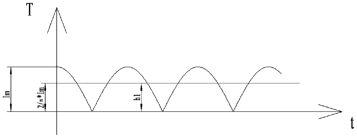
[0002] A motor is a machine that provides rotational speed for other machines. In the prior art, three-phase motors are widely used. Dismantling its structure means that alternating current is input into the stator and rotor to generate rotational torque to balance the load torque for rotation. Alternating current is a For a sinusoidal fluctuating current, the torque generated on the stator and rotor is proportional to the absolute value of the current. Therefore, the input torque on the stator and rotor also fluctuates, and its average torque is equal to the load torque. When the input torque fluctuates, it will cause The fluctuation of the spindle speed, in some occasions with high requirements on the speed, cannot meet the requirements of the application.

Method used


Image

  • Multi-phase iron core feedback compensation pulse motor
  • Multi-phase iron core feedback compensation pulse motor
  • Multi-phase iron core feedback compensation pulse motor

Examples


Embodiment Construction

[0024] The technical solutions in the embodiments of the present invention will be clearly and completely described below in conjunction with the accompanying drawings in the embodiments of the present invention. Obviously, the described embodiments are only a part of the embodiments of the present invention, rather than all the embodiments. Based on the embodiments of the present invention, all other embodiments obtained by those of ordinary skill in the art without creative work shall fall within the protection scope of the present invention.

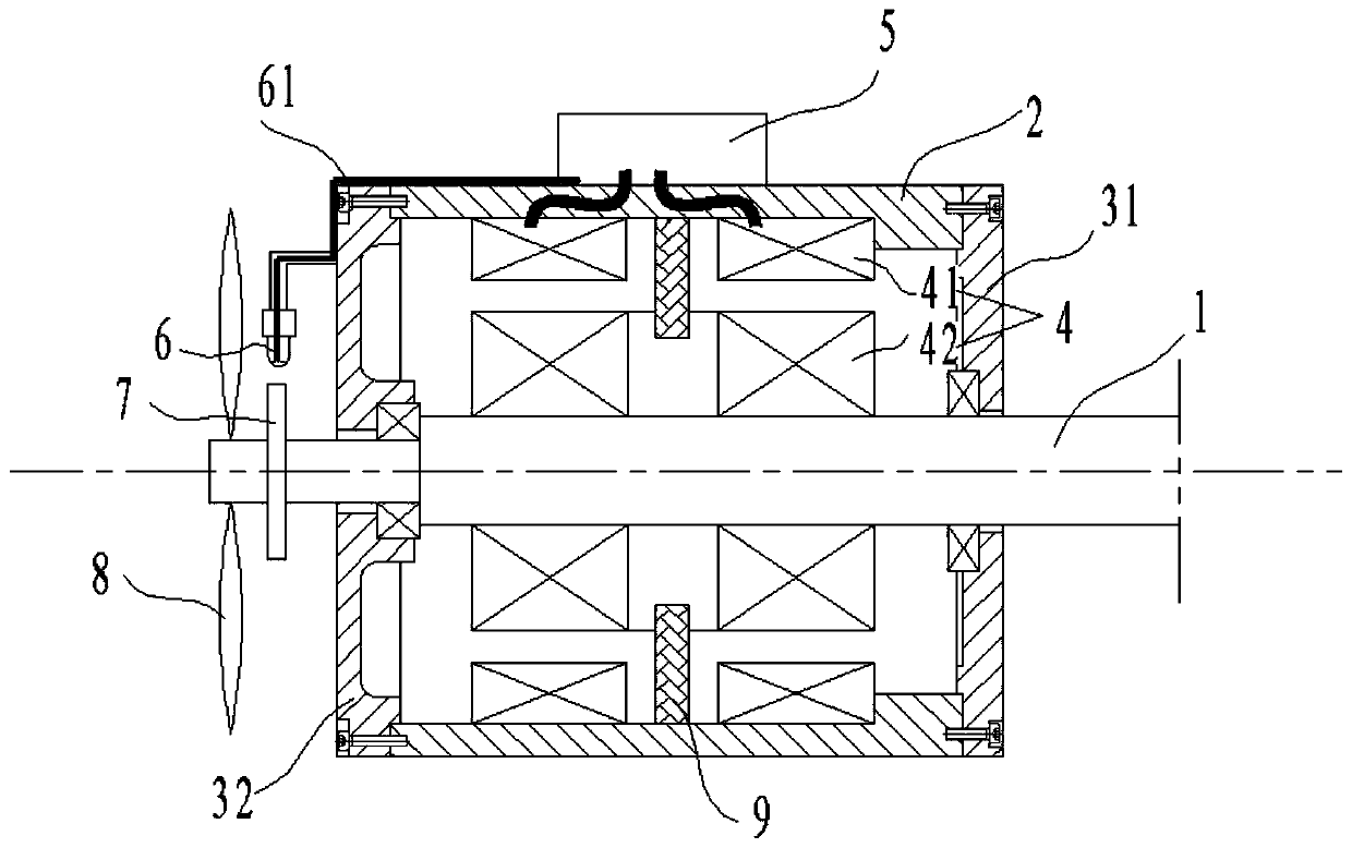
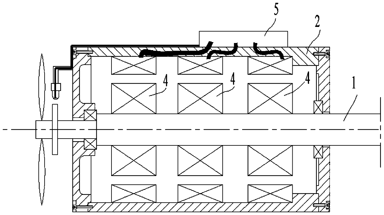
[0025] Such as figure 1 As shown, a multi-phase iron core feedback compensation pulse motor includes a main shaft 1, a housing 2, a front end cover 31, a rear end cover 32, a control box 5 and at least two excitation pairs 4, each excitation pair 4 includes a stator 41 With the rotor 42, the two ends of the casing 2 are fixedly connected with the front cover 31 and the rear cover 32 to form a closed casing. The main shaft 1 is mounted on ...


PUM


Abstract

The invention discloses a multi-phase iron core feedback compensation pulse motor. The motor comprises a main shaft, a machine shell, a front end cover, a rear end cover, a control box and at least two excitation pairs. Each excitation pair comprises a stator and a rotor; and two ends of the machine shell are fixedly connected with the front end cover and the rear end cover to form a closed shell.The main shaft is installed on the machine shell or the end cover through bearing double-end supporting, the stators are installed on an inner wall of the machine shell, the rotors are installed onthe main shaft, the rotors coincide with the stators in axial position and are adjacent to the stators in radial position, the control box is installed on the outer wall of the machine shell, and thecontrol box is connected with an external power supply and delivers currents to the stators respectively. The motor further comprises a speed sensor, the speed sensor detects a rotating speed of the main shaft, converts the rotating speed into an electric signal and transmits the electric signal to the control box, and the control box receives a rotating speed change of the main shaft and controlsa phase of a current input to each excitation pair.

Description

Technical field [0001] The invention relates to the field of motors, in particular to a multiphase iron core feedback compensation pulse motor. Background technique [0002] The motor is a machine that provides the rotation speed for other machines. In the prior art, the three-phase motor is widely used. The structure of the three-phase motor is disassembled. The alternating current is input into the stator and rotor to generate a rotating torque to balance the load torque and rotate. For sinusoidal fluctuating currents, the torque produced on the stator and rotor is proportional to the absolute value of the current. Therefore, the input torque on the stator and rotor also fluctuates. The average torque is equal to the load torque. When the input torque fluctuates, it will cause The fluctuation of the spindle speed cannot meet the requirements in some occasions that require high speed. Summary of the invention [0003] The purpose of the present invention is to provide a multi-ph...

Claims


Application Information

Patent Timeline
Patent Type & Authority Applications(China)
IPC IPC(8): H02K5/04H02K5/22H02K11/30H02K11/21H02P23/04H02P23/14
CPCH02K5/04H02K5/225H02P23/04H02P23/14H02K11/21H02K11/30
Inventor 陈雪芝
Owner SUZHOU WEIGENA INFORMATION TECH CO LTD
Learn More