Supercharge Your Innovation With Domain-Expert AI Agents!

Vibration type actuator and manufacturing method of vibration type actuator

A manufacturing method, vibration-type technology, applied in the direction of instruments, generators/motors, piezoelectric effect/electrostrictive or magnetostrictive motors, etc., can solve the problem of actuator performance degradation

Pending Publication Date: 2020-07-24
CANON KK
View PDF2 Cites 0 Cited by
  • Summary
  • Abstract
  • Description
  • Claims
  • Application Information

AI Technical Summary

Problems solved by technology

Therefore, in the case where one contact element is driven by a plurality of vibrating elements using one booster circuit (i.e., a common AC signal), depending on the combination of vibrating elements, the performance of the actuator may be degraded in some cases.

Method used


Image

  • Vibration type actuator and manufacturing method of vibration type actuator
  • Vibration type actuator and manufacturing method of vibration type actuator
  • Vibration type actuator and manufacturing method of vibration type actuator

Examples


Embodiment Construction

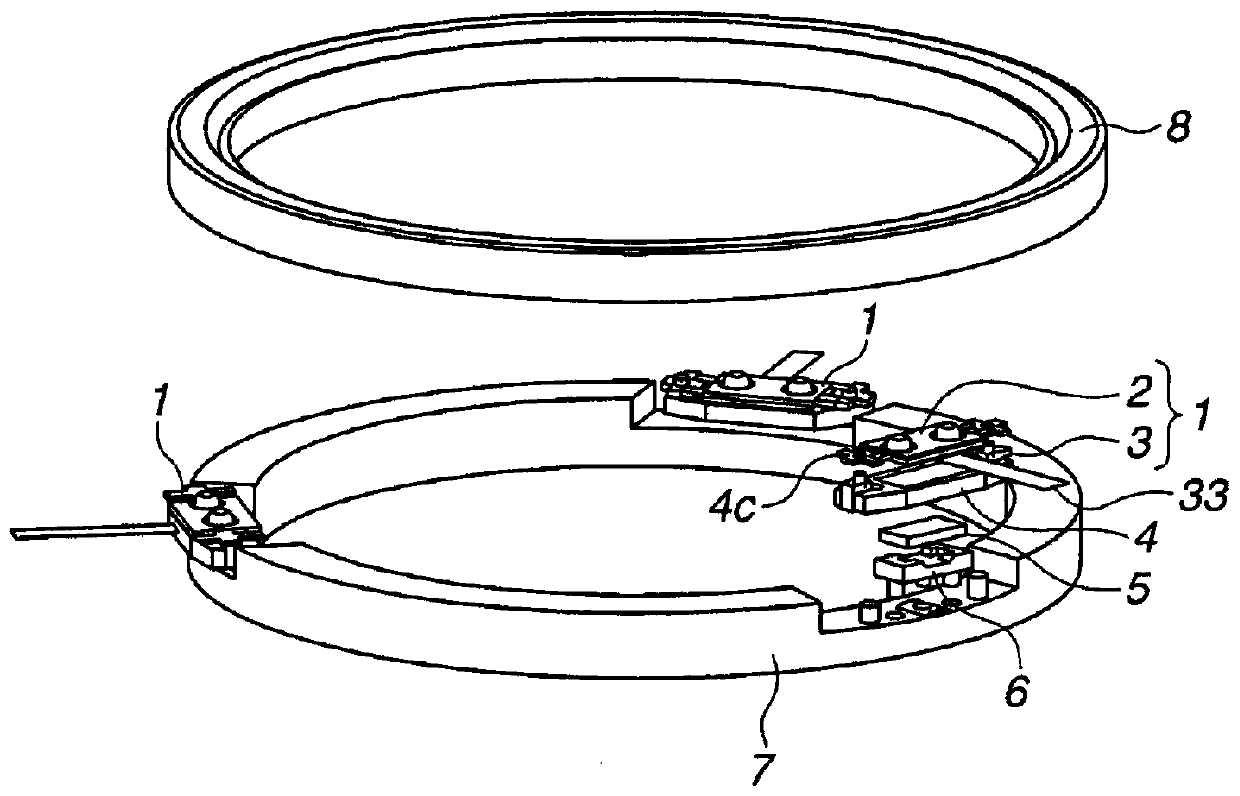
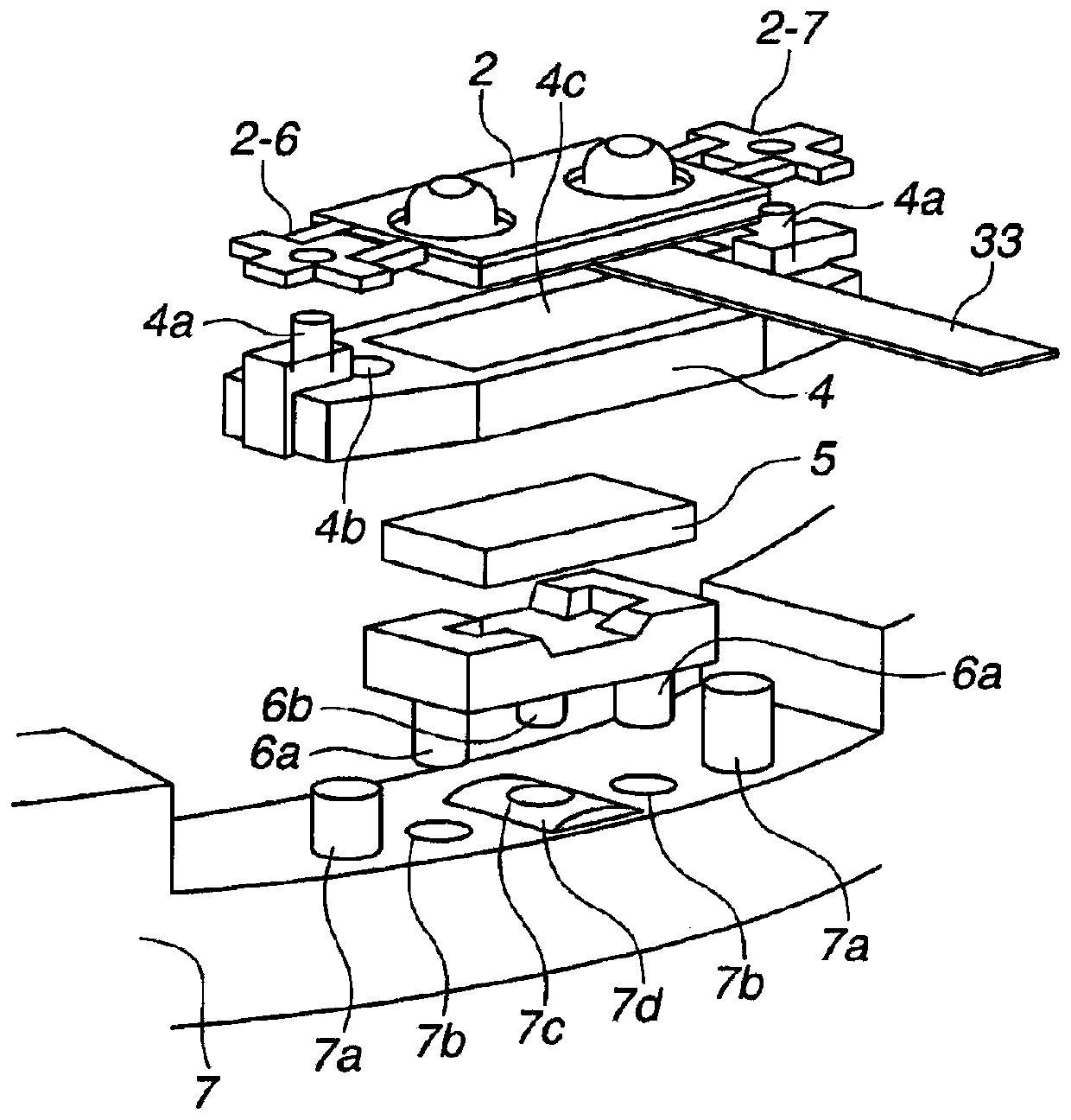
[0017] First, refer to Figures 8A to 9C General techniques are described.

[0018] Figure 8A is the plan view of the vibrating element, Figure 8B is a side view of the vibrating element. exist Figure 8A with 8B Among them, a vibrating element 1 includes an electric energy-mechanical energy conversion element (piezoelectric element) 3 having a rectangular (quadrilateral) thin plate shape and an elastic element 2 integrally bonded to (one plane of) the piezoelectric element 3 .

[0019] The elastic element 2 comprises a main part 2-3 and a support part 2-4.

[0020] The main part 2-3 comprises a base part 2-1 and two protrusions 2-2. The base portion 2 - 1 having a rectangular thin plate shape vibrates together with the piezoelectric element 3 . The protrusion 2-2 protrudes from one plane of the base portion 2-1 (the plane of the elastic member 2 opposite to the plane to which the piezoelectric element 3 is bonded). For example, as discussed in Japanese Patent Applic...


PUM


Abstract

The invention relates to a vibration type actuator and a manufacturing method of the vibration type actuator. The vibration type actuator includes vibrating elements and a contact element that is brought into contact with each other in a first direction. The vibration of the vibrating elements includes vibration in a first vibration mode in the first direction and vibration in a second vibration mode in a second direction intersecting the first direction. In the vibrating elements, a minimum value of a resonance frequency in the second vibration mode is greater than or equal to a maximum valueof a resonance frequency in the first vibration mode, and a ratio of a difference between the maximum value and the minimum value of the resonance frequency in the second vibration mode to the minimum value of the resonance frequency in the second mode is less than or equal to a predetermined value.

Description

technical field [0001] The present disclosure relates to vibration-type actuators. Background technique [0002] Conventionally, vibration type actuators have been proposed. The vibration type actuator is configured such that a contact element in contact with a vibration element (elastic element, piezoelectric element) is driven by vibration excited by the vibration element (the vibration element and the contact element move relatively). [0003] For example, Japanese Patent Application Laid-Open No. 2011-259559 discloses an actuator including two vibration elements or a plurality of vibration elements. The two vibrating elements are linearly driven, or the plurality of vibrating elements are rotationally driven. [0004] However, in the vibrating element, the resonance frequency changes due to the dimensional changes of the elastic element and the piezoelectric element. Therefore, in the case where one contact element is driven by a plurality of vibrating elements using ...

Claims


Application Information

Patent Timeline
IPC IPC(8): H02N2/02H02N2/06G02B7/09G03B13/36
CPCH02N2/02H02N2/06G02B7/09G03B13/36H02N2/0015H02N2/103H02N2/22H02N2/008H02N2/028H02N2/026H02N2/001
Inventor 木村笃史
Owner CANON KK
Features
  • R&D
  • Intellectual Property
  • Life Sciences
  • Materials
  • Tech Scout
  • Unparalleled Data Quality
  • Higher Quality Content
  • 60% Fewer Hallucinations
Learn More