Wrist nursing rehabilitation training device
A trainer and wrist technology, applied in the field of wrist rehabilitation training equipment, can solve the problems of long treatment period, single training method, and low bionic simulation, so as to improve toughness, reduce the probability of secondary injury, and improve the effect Effect
- Summary
- Abstract
- Description
- Claims
- Application Information
AI Technical Summary
Problems solved by technology
Method used
Image

Examples
specific Embodiment approach 1
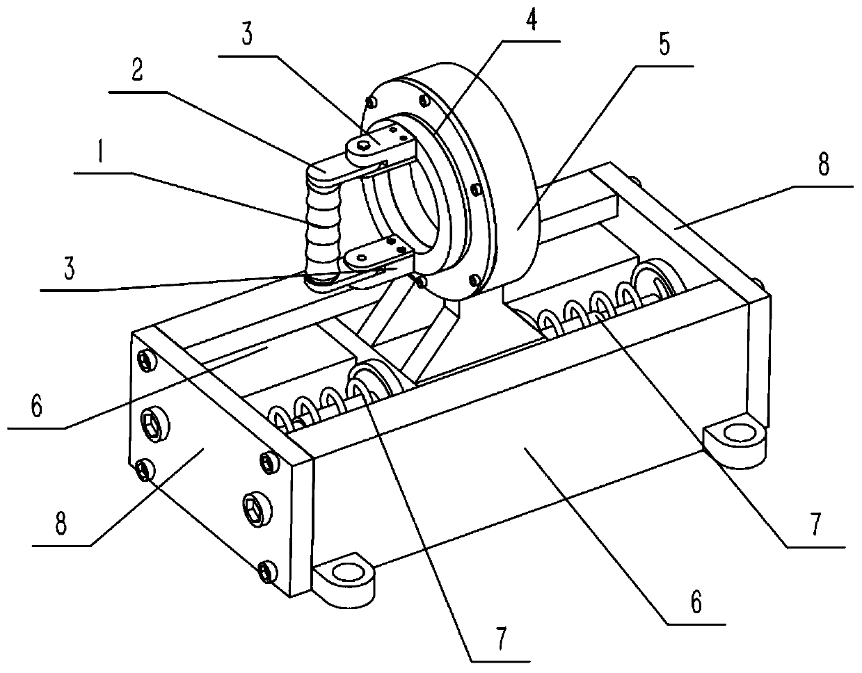
[0033] Combine below Figure 1-11 Describe this embodiment, a nursing wrist rehabilitation training device, including a handle cover 1 and a spring column 7, the toy injection molding machine also includes a gripping mechanism 2, a resistance mechanism 3, a rotating mechanism 4, a pushing mechanism 5, and a supporting mechanism 6 and a limit mechanism 8, the handle cover 1 is sleeved on the holding mechanism 2, and the resistance mechanism 3 is provided with two, and the two resistance mechanisms 3 are respectively connected to the upper and lower sides of the rear end of the holding mechanism 2 in rotation. Both resistance mechanisms 3 are fixedly connected to the front end of the rotating mechanism 4, the rotating mechanism 4 is connected to the front end of the pushing mechanism 5 in rotation, and two spring columns 7 are provided, and the two spring columns 7 are fixedly connected to the pushing mechanism respectively. 5, the front and rear ends of the lower end, two suppo...
specific Embodiment approach 2
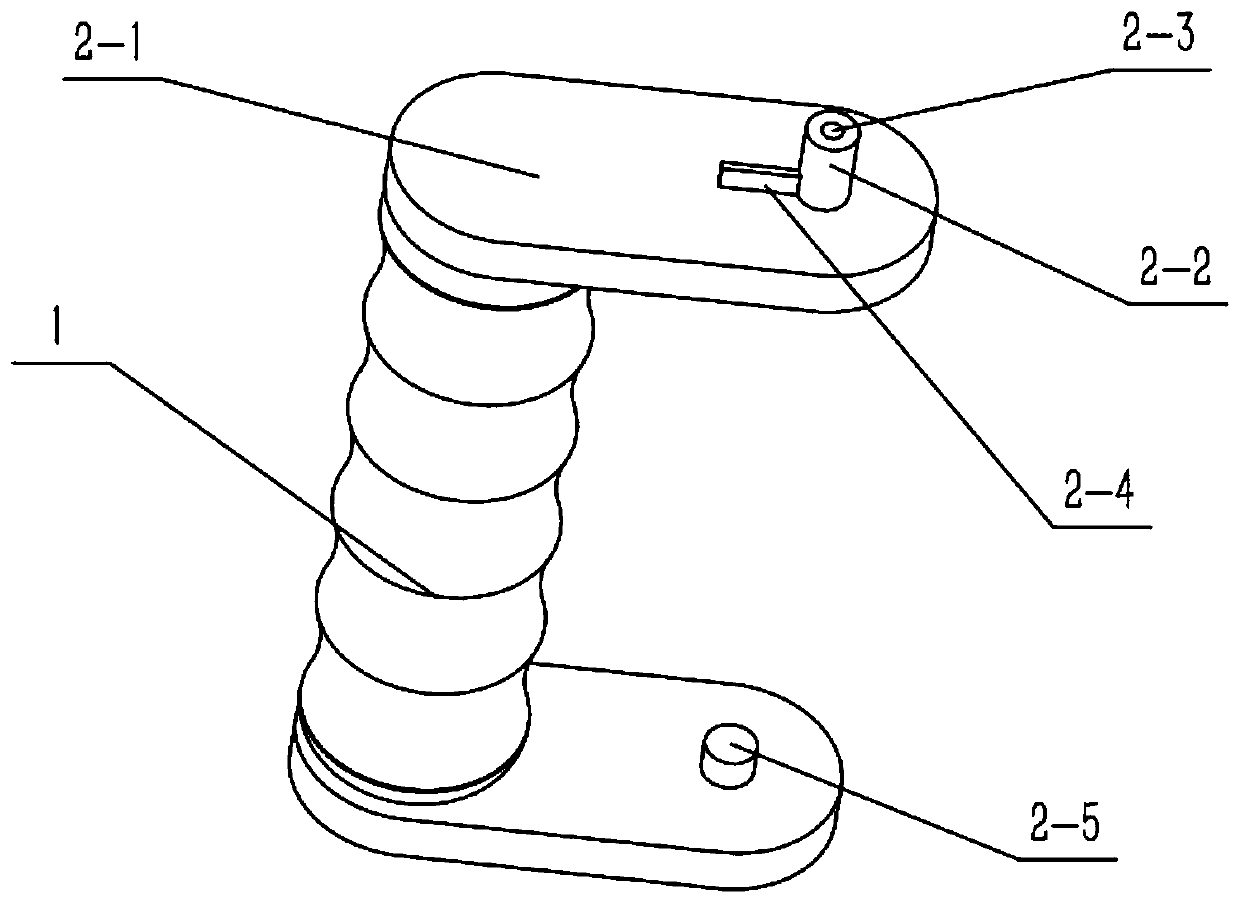
[0036] Combine below Figure 1-11 This embodiment will be described. This embodiment will further describe Embodiment 1. The holding mechanism 2 includes a holding frame 2-1, a rotating shaft I2-2, a threaded hole I2-3, a limiting block I2-4, and a rotating shaft II2. -5, two rotating shafts I2-2 are provided, and the two rotating shafts I2-2 are respectively fixedly connected to the outside of the rear end of the holding frame 2-1, and the outsides of the two rotating shafts I2-2 are provided with threads There are two holes I2-3, two restriction blocks I2-4, and the two restriction blocks I2-4 are respectively fixedly connected to the outside of the rear end of the holding frame 2-1, and two rotation shafts II2-5 are provided, two Two rotating shafts II 2-5 are respectively fixedly connected to the inner side of the rear end of the holding frame 2-1, and the two rotating shafts II 2-5 are respectively coaxially arranged with the two rotating shafts I2-2, and the two resistan...
specific Embodiment approach 3
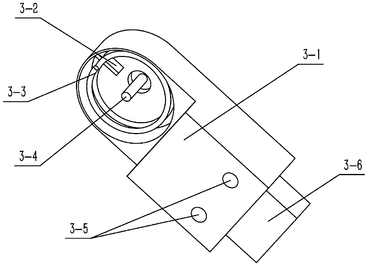
[0039] Combine below Figure 1-11 Describe this embodiment, this embodiment will further explain the second embodiment, the resistance mechanism 3 includes a resistance frame 3-1, a restriction block II 3-2, a spring I 3-3, a tightening bolt 3-4, and a threaded hole I 3-5 , connecting block 3-6, fixed plate 3-7, rotating hole 3-8 and fixing bolt I3-9, the restriction block II3-2 is fixedly connected to the inner side of the front end of the resistance frame 3-1, and the spring I3-3 It is arranged on the inner side of the front end of the resistance frame 3-1, and the two ends of the spring I3-3 are respectively fixedly connected with the restriction block I2-4 and the restriction block II3-2, and the tightening bolt 3-4 passes through the spring I3-3, and passes through The thread fits and is fixedly connected in the threaded hole I2-3, and two threaded holes I3-5 are provided, and the two threaded holes I3-5 are arranged side by side on the inner side of the resistance frame ...
PUM
 Abstract
Description
Claims
Application Information
 - R&D
- Intellectual Property
- Life Sciences
- Materials
- Tech Scout
- Unparalleled Data Quality
- Higher Quality Content
- 60% Fewer Hallucinations
Browse by: Latest US Patents, China's latest patents, Technical Efficacy Thesaurus, Application Domain, Technology Topic, Popular Technical Reports.
© 2025 PatSnap. All rights reserved.Legal|Privacy policy|Modern Slavery Act Transparency Statement|Sitemap|About US| Contact US: help@patsnap.com