Peep-proof password device and password peep-proof method

A cipher device and password technology, applied in the field of cipher devices, can solve the problems of operation risk, password easy to be stolen by prying eyes, password peeping and theft, etc., and achieve the effect of reducing risks.

Inactive Publication Date: 2020-07-28
北京隆普智能科技有限公司
View PDF5 Cites 0 Cited by
  • Summary
  • Abstract
  • Description
  • Claims
  • Application Information

AI Technical Summary

Problems solved by technology

In the process of entering the password through the existing cipher, the password may be stolen by peeping. In the prior art, a protective cover that half surrounds the upper part of the cipher is usually set on the front of the cipher, and some openings are set on the protective cover. Observe the opening of the key on the cipher device to prevent the leakage of the password, but even with the protection of the protective cover, the operation of entering the password on the cipher device is a relatively exposed operation, and the password is still relatively easy to be peeped and stolen, resulting in Operation is risky

Method used


Image

  • Peep-proof password device and password peep-proof method
  • Peep-proof password device and password peep-proof method
  • Peep-proof password device and password peep-proof method

Examples


Embodiment 1

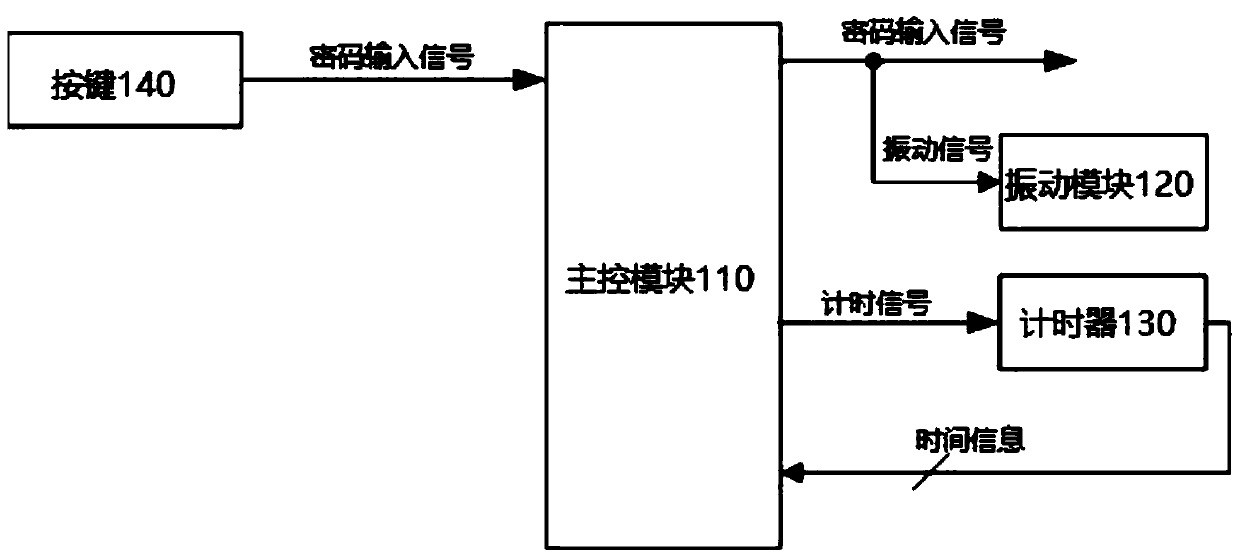
[0023] see figure 1 , figure 1 It is a schematic circuit diagram of an anti-peeping cipher provided by an embodiment of the present application.

[0024] The application provides an anti-peeping cipher, including: a main control circuit 110, a vibration module 120 and a timer 130, and the main control circuit 110, the vibration module 120 and the timer 130 are all arranged on the cipher body (not shown in the figure). )internal.

[0025] Wherein, the main control circuit 110 receives the password input signal generated by the user operating the key 140, and controls the timer 130 to record the duration of the password input signal.

[0026] Specifically, the main control circuit 110 is electrically connected with the key 140 of the cipher body to receive the password input signal sent by the user operation (for example: pressing) the key 140 of the cipher body; When the main control circuit 110 receives the password input signal generated by the user through the operation b...

Embodiment 2

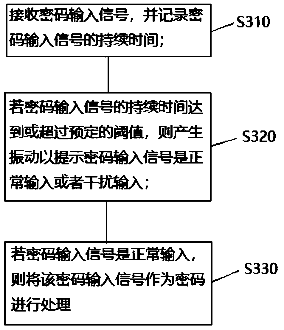
[0041] See image 3 , image 3 It is a flow chart of the password anti-peeping method provided by the implementation of this application.

[0042] The present application also provides a password anti-peeping method, including the following steps:

[0043] Step S310, receiving the password input signal, and recording the duration of the password input signal;

[0044] When the user presses the button of the cipher device, the button sends a password input signal to the main control circuit. After the main control circuit receives the password input signal, it sends a timing signal to the timer to reset the timer and start counting. Press the button, the timer stops counting.

[0045] On the basis of the above, after receiving the password input signal, the button sound of pressing the button starts to be issued, so as to prompt the user to press the button while disturbing the observation of the peeping person.

[0046] Step S320, if the duration of the password input sign...


PUM


Abstract

The invention relates to the technical field of password devices, in particular to a peep-proof password device and a password peep-proof method, and the peep-proof password device comprises a main control circuit, a vibration module and a timer; wherein the main control circuit receives a password input signal and controls the timer to record the duration of the password input signal; if the duration of the password input signal reaches or exceeds a preset threshold value, the main control circuit drives the vibration module to vibrate so as to prompt that the password input signal is normally input or disturbs input; and if the password input signal is normally input, the main control circuit processes the password input signal as a password. According to the invention, the duration of pressing the key by the user is processed as a part of the password, so that the peeper cannot know the correct password even if seeing the character sequence input by the user, and the peeper is effectively interfered.

Description

technical field [0001] The present application relates to the technical field of ciphers, in particular to an anti-peeping cipher and a password anti-peeping method. Background technique [0002] A cipher is a device for entering passwords. Keys for entering passwords are set on the front of the cipher, for example: number keys 1-number 9, delete key, confirmation key, ﹟ key, ﹡ key, etc. button. In the process of entering the password through the existing cipher, the password may be stolen by peeping. In the prior art, a protective cover that half surrounds the upper part of the cipher is usually set on the front of the cipher, and some openings are set on the protective cover. Observe the opening of the key on the cipher device to prevent the leakage of the password, but even with the protection of the protective cover, the operation of entering the password on the cipher device is a relatively exposed operation, and the password is still relatively easy to be peeped and s...

Claims


Application Information

Patent Timeline
Patent Type & Authority Applications(China)
IPC IPC(8): G06F21/83G06F3/023
CPCG06F3/023G06F21/83
Inventor 苑贵全
Owner 北京隆普智能科技有限公司
Why Eureka
Try Eureka