
Engine signal identification method and device

An identification method and engine technology, applied in digital transmission systems, electrical components, transmission systems, etc., can solve problems such as inability to take into account different signal input forms

Active Publication Date: 2020-07-28
WEICHAI POWER CO LTD
View PDF8 Cites 0 Cited by
  • Summary
  • Abstract
  • Description
  • Claims
  • Application Information

AI Technical Summary

Problems solved by technology

[0006] Embodiments of the present invention provide a method and device for identifying engine signals to at least solve the technical problem in the related art that the same ECU data cannot accommodate different signal input forms

Method used


Image

  • Engine signal identification method and device
  • Engine signal identification method and device
  • Engine signal identification method and device

Examples


Embodiment 1

[0032] According to an embodiment of the present invention, an embodiment of a method for identifying an engine signal is provided. It should be noted that the steps shown in the flowcharts of the accompanying drawings can be executed in a computer system such as a set of computer-executable instructions, and , although a logical order is shown in the flowcharts, in some cases the steps shown or described may be performed in an order different from that shown or described herein.

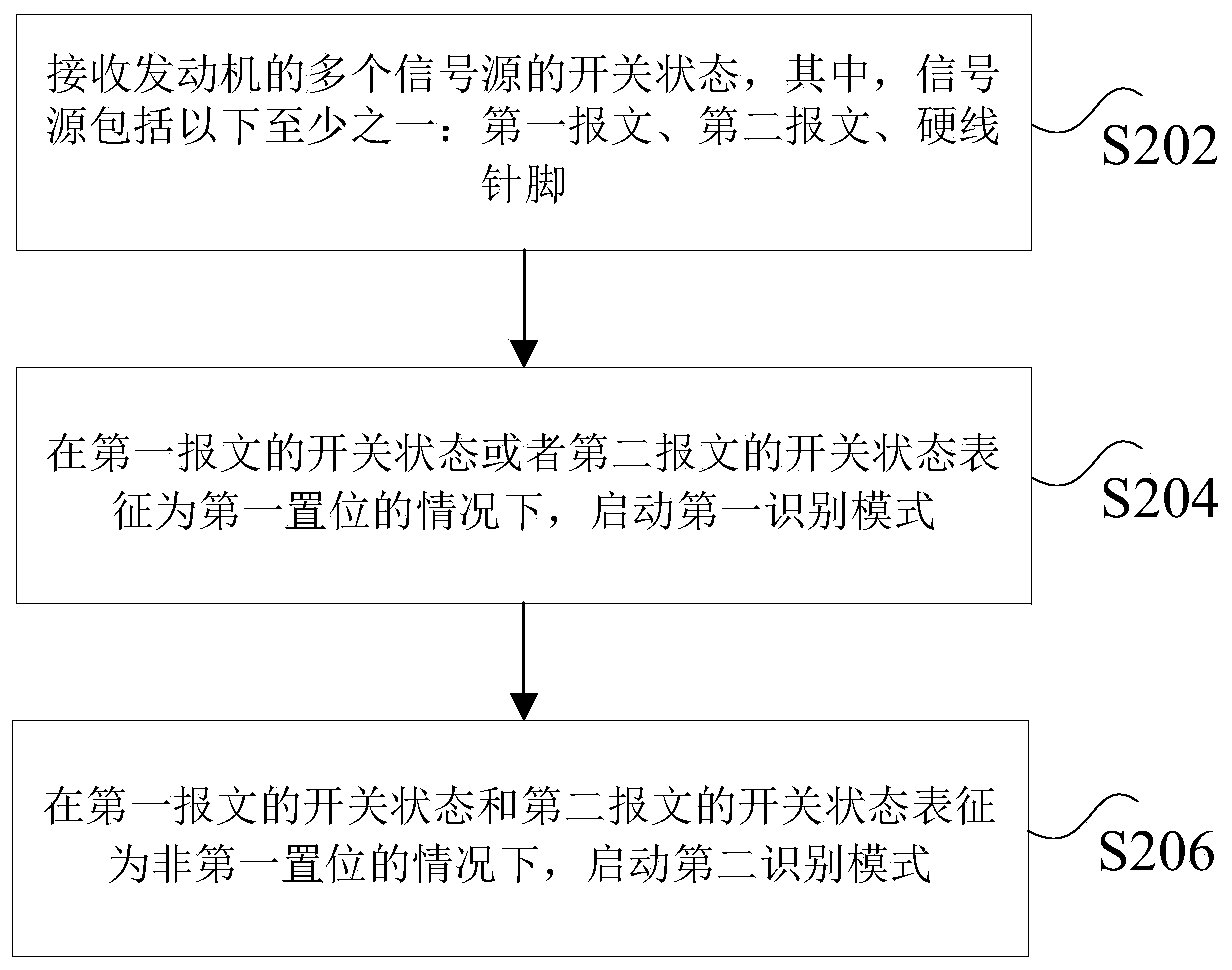
[0033] figure 2 is a flow chart of a method for identifying an engine signal according to an embodiment of the present invention, such as figure 2 As shown, the identification method of the engine signal comprises the following steps:

[0034] Step S202, receiving switch states of multiple signal sources of the engine, wherein the signal source includes at least one of the following: first message, second message, hardwired pin;

[0035] The above-mentioned signal source is used to send signals in...

Embodiment 2

[0066] According to another aspect of the embodiment of the present invention, a device for identifying an engine signal is also provided, Figure 4 is a schematic diagram of an engine signal identification device according to an embodiment of the present invention, such as Figure 4 As shown, the identification device of the engine signal includes: a receiving module 42 , a first starting module 44 and a second starting module 46 . The identification device of the engine signal will be described in detail below.

[0067] The receiving module 42 is configured to receive the switching states of multiple signal sources of the engine, wherein the signal source includes at least one of the following: a first message, a second message, and a hardwire pin;

[0068] The first starting module 44 is connected to the above-mentioned receiving module 42, and is used to start the first identification mode when the switch state of the first message or the switch state of the second messag...

Embodiment 3

[0079] According to another aspect of the embodiments of the present invention, there is also provided a storage medium, the storage medium includes a stored program, wherein when the program is running, the device where the storage medium is located is controlled to execute any one of the above methods.


PUM


Abstract

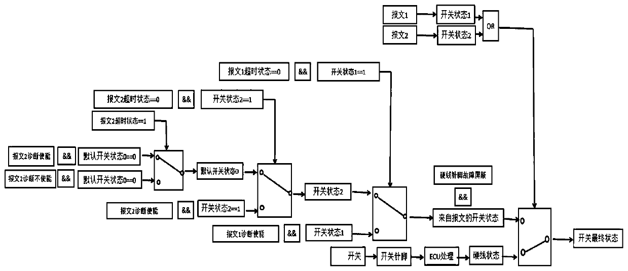
The invention discloses an engine signal identification method and device. The method comprises the steps of receiving on-off states of a plurality of signal sources of an engine, wherein the signal sources comprise at least one of a first message, a second message and a hard wire pin; starting a first identification mode under the condition that the on-off state of the first message or the on-offstate of the second message is represented as a first setting; when the on-off state of the first message and the on-off state of the second message are represented as non-first setting, starting a second identification mode; wherein the first identification mode is a mode of shielding signals input in a hard wire form and identifying signals input in a message form at the same time; wherein thesecond identification mode is a mode of simultaneously shielding the signals input in the message form and identifying the signals input in the hard wire form. The technical problem that the same ECUdata cannot consider different signal input forms in the prior art is solved.

Description

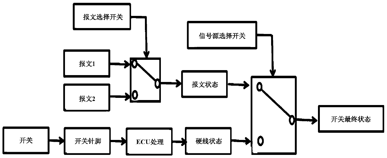
technical field [0001] The present invention relates to the technical field of engine signal processing, in particular to a method and device for identifying engine signals. Background technique [0002] In the prior art, the signal processing logic is independent, and the signal input is selected through data calibration in the form of a message or a hard-wired form. figure 1 is a schematic diagram of engine signal recognition in the prior art, such as figure 1 As shown, in the engine signal recognition in the prior art, if the signal is input in the form of a message, if the customer needs to change it to a hard-wire input, the engine needs to redevelop the program. [0003] In addition, for the same order number, if the customer needs to flexibly choose the signal input form according to the sales characteristics (for example: high-end models use message form input, low-end vehicles use hard-wire form input), the existing technology cannot satisfy, and a new contract nee...

Claims


Application Information

Patent Timeline
Patent Type & Authority Applications(China)
IPC IPC(8): H04L12/26
CPCH04L43/08
Inventor 冯春涛
Owner WEICHAI POWER CO LTD
Learn More