Cutting slag gas-liquid two-phase clearing device
A cleaning device and gas-liquid technology, applied in the field of mechanical processing, can solve problems such as slag collection and growth, and achieve the effects of avoiding slag collection, avoiding sintering effect, and preventing sticking of cutting slag
Inactive Publication Date: 2020-08-04
广东库迪二机激光装备有限公司
View PDF0 Cites 1 Cited by
- Summary
- Abstract
- Description
- Claims
- Application Information
AI Technical Summary
Problems solved by technology
[0005] (2) Sintering on the slag formed in the early stage, causing the slag to grow;
Method used
View moreImage
Smart ImageViewing Examples
Examples
Embodiment 2
[0025] Embodiment 2, on the basis of embodiment 1, as Figure 4 As shown, a certain number of spray holes are distributed and processed on one side of the slender tube, and the cleaning liquid with a certain pressure in the tube is sprayed out from the spray holes.
Login to View More PUM
 Abstract
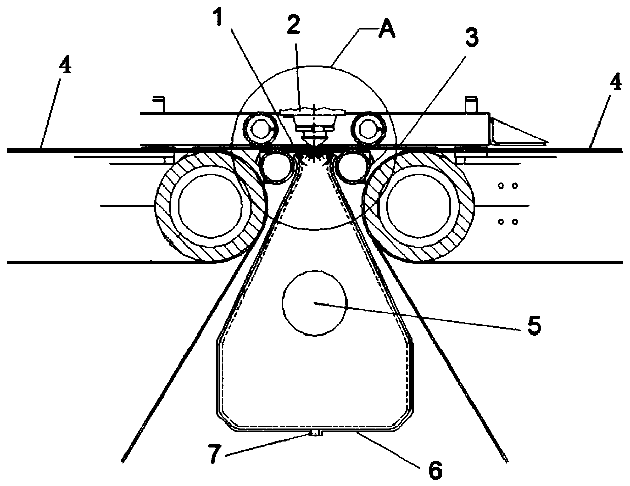
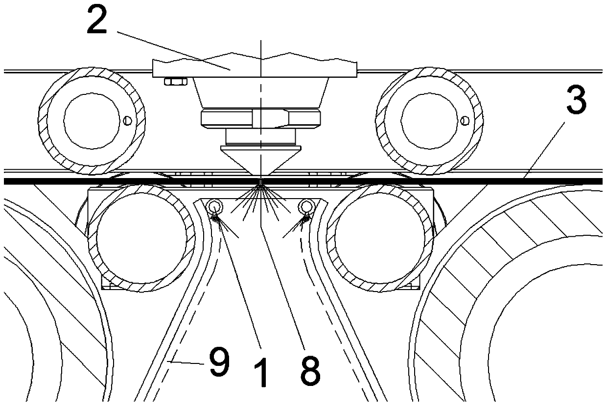
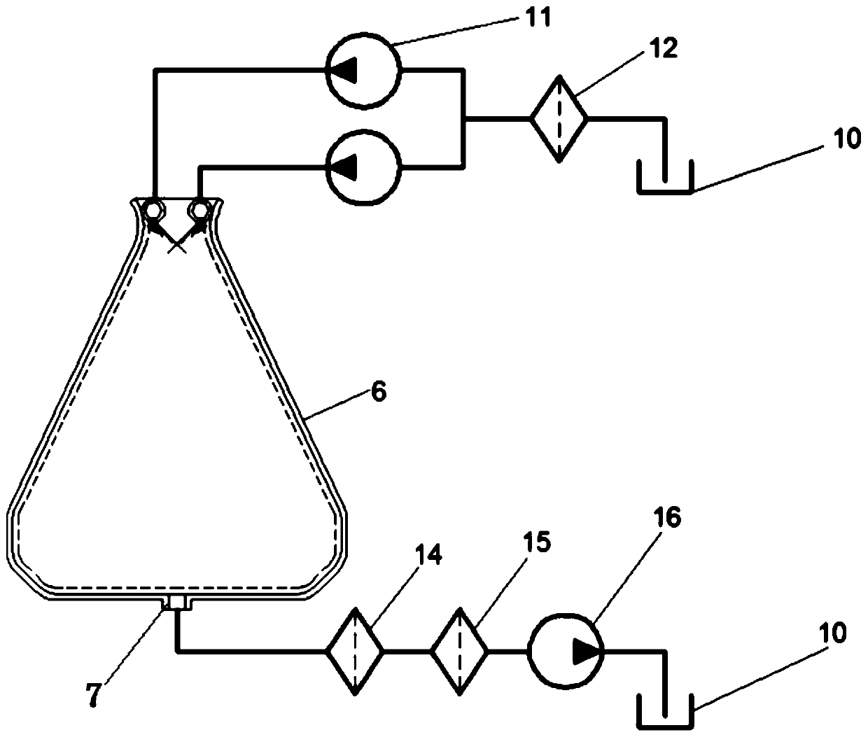
The invention discloses a cutting slag gas-liquid two-phase clearing device. The device comprises a slag clearing box, a cutting head, a spraying pump, a water tank, a reflux pump and a water outlet fine filtering device, wherein the slag clearing box is installed below the cutting head, two spraying pipes are arranged in the top of the slag clearing box and connected with the spraying pump, the water inlet end of the spraying pump is connected with the water inlet fine filtering device, the water inlet end of the water inlet fine filtering device is connected with the water tank, the middle of the slag clearing box is provided with a dust removing suction opening used for discharging cleaning liquid spray and steam, and a dust removing water pumping opening used for discharging cleaning liquid is formed in the lower portion of the slag clearing box. According to the device, the water-based cleaning liquid is used for forming a spacer liquid film on the surface of a laser seam structural member and forming the spray in a laser seam space, cutting slag is rapidly cooled, the sintering effect of the cutting slag is avoided, slag collection is avoided, and meanwhile, the liquid film on the surface of the laser seam structural member can prevent the cutting slag from being sintered and adhered and can also scour the cutting slag.
Description
technical field [0001] The invention relates to the technical field of mechanical processing, in particular to a gas-liquid two-phase cleaning device for slag cutting. Background technique [0002] It is a common phenomenon in the industry that the slag generated by laser cutting accumulates on the cutting machine. The use of dust removal fans can improve the air quality of the environment, but slag collection cannot be avoided. [0003] During the cutting process, the slag produced has two forms, namely dust and particles. Under the action of the high-speed airflow injected by the cutting head, the high-temperature slag flies away from the slit and encounters obstacles, causing three consequences: [0004] (1) Sticking to obstacles to form slag-collecting particles; [0005] (2) Sintering on the slag formed in the early stage, causing the slag to grow; [0006] (3) Rebound to support belts, blanking parts and blanks. [0007] The problem of slag collection will serious...
Claims
Login to View More Application Information
Patent Timeline
 IPC IPC(8): B23K26/38B23K26/70
CPCB23K26/38B23K26/702B23K26/703
Inventor 王建业谢嘉伟张朋杨燕萍
Owner 广东库迪二机激光装备有限公司
- R&D Engineer
- R&D Manager
- IP Professional
Why Eureka
- Industry Leading Data Capabilities
- Powerful AI technology
- Patent DNA Extraction
Eureka Blog
Learn More Browse by: Latest US Patents, China's latest patents, Technical Efficacy Thesaurus, Application Domain, Technology Topic, Popular Technical Reports.
© 2024 PatSnap. All rights reserved.Legal|Privacy policy|Modern Slavery Act Transparency Statement|Sitemap|About US| Contact US: help@patsnap.com


