Physical quantity inspection device

An inspection device and technology for physical quantities, applied in the field of physical quantity inspection, can solve problems such as inconvenience, large size, and inaccuracy

Active Publication Date: 2020-08-07
王娜娜
View PDF7 Cites 0 Cited by
  • Summary
  • Abstract
  • Description
  • Claims
  • Application Information

AI Technical Summary

Problems solved by technology

Existing inspection equipment is inconvenient to use in a dusty environment, or its volume is large, inconvenient or inaccurate to use

Method used


Image

  • Physical quantity inspection device
  • Physical quantity inspection device
  • Physical quantity inspection device

Examples


specific Embodiment approach 1

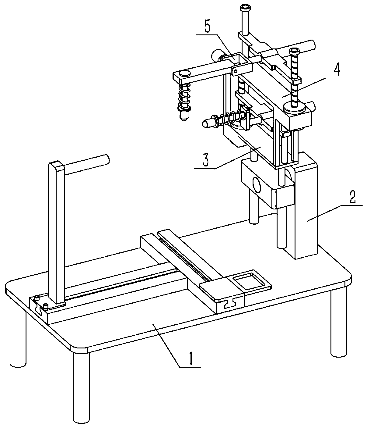
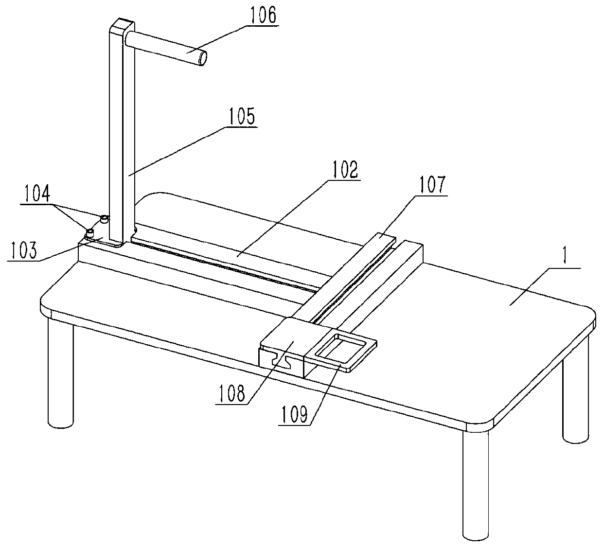
[0028] Such as Figure 1-7 As shown, a physical quantity inspection device includes a base block I306, a slide rod I307, a limit piece I308, a stop piece I309, a compression spring I310, a universal joint I311 and a universal ball I312. The left and right ends of the rod I307 and the slide rod I307 are fixedly connected to the contact piece I309 and the limit piece I308 respectively. Between the pieces I309, the universal joint I311 is fixedly connected to the left end of the counter piece I309, and the universal ball I312 is installed in the universal joint I311. The end surface to be detected is contacted with the universal ball I 312 and the universal ball I 312 is contracted to a certain extent. The contraction is that the compression spring I 310 continues to shrink due to the compression of the universal ball I 312 by the end surface to be detected. If the end face to be detected is horizontal, pass the end face to be detected over the universal ball I312 in a straight ...

specific Embodiment approach 2

[0030] Such as Figure 1-7 As shown, the physical quantity inspection device also includes a matching plate 503, a sliding rod II 504, a limit piece II 505, a stop piece II 506, a compression spring II 507, a universal joint II 508 and a universal ball II 509. The left side of the adjusting plate 503 is slidingly connected to The sliding rod II504, the upper and lower ends of the sliding rod II504 are fixedly connected with the limit piece II505 and the abutment piece II506 respectively, the limit piece II505 is located above the allocation plate 503, and the compression spring II507 is set on the slide bar II504 and is located between the allocation plate 503 and the abutment plate 503. Between the pieces II506, the universal joint II508 is fixedly connected to the lower end of the supporting piece II506, and the universal ball II509 is installed in the universal joint II508; the universal ball II509 is located above the left side of the universal ball I312, and the axis of th...

specific Embodiment approach 3

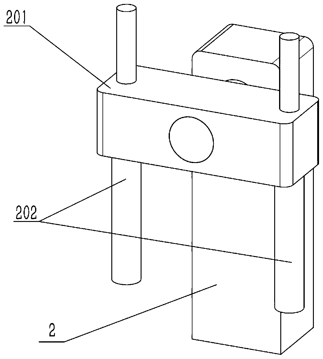
[0032] Such as Figure 1-7As shown, the physical quantity inspection device also includes a base II3, a motor II301, a lead screw I302, a round rod I303, and an adjustment table I304. The shaft is fixed, the round rod I303 is fixed on the rear side of the base II3, the front side of the adjustment table I304 is threaded with the screw I302, the rear side of the adjustment table I304 is slidingly connected with the round rod I303, and the base block I306 is installed on the adjustment table On the left side of I304. Start the motor Ⅱ301, the output shaft of the motor Ⅱ301 drives the screw Ⅰ302 to rotate, the screw Ⅰ302 drives the adjustment table Ⅰ304 to rise and fall, the adjustment table Ⅰ304 can adjust the height of the universal ball Ⅰ312, and then the object to be measured can be kept still. The position of the universal ball I312 can be changed to check different positions of the end faces to be tested, and the distance between the universal ball I312 and the universal b...


PUM


Abstract

The invention relates to the field of physical quantity inspection, in particular to a physical quantity inspection device. The device comprises a base block I, a sliding rod I, a limiting piece I, anabutting piece I, a compression spring I, a universal joint I and a universal ball I; the motion trail of the universal ball I is used as a reference; the motion direction of the universal ball II can be adjusted, so that the motion trails between the universal ball II and the universal ball II can be parallel or vertical or at other angles, the arc end surface or plane of an object can be conveniently inspected, the plane of a simple plate-shaped object can be inspected, and the arc end surface of a circular truncated cone or a cylinder or two planes at different positions of a stepped object can also be inspected; if the sliding rod I or the sliding rod II slides, the arc end surface of the to-be-detected object is non-circular or the plane is uneven; scales are arranged on the slidingrod I or the sliding rod II or a pressure gauge is arranged, so that the flatness change amount of the to-be-measured end surface is convenient to observe.

Description

technical field [0001] The invention relates to the field of physical quantity inspection, in particular to a physical quantity inspection device. Background technique [0002] In order to calculate the needs of various physical quantities, some physical quantities are artificially selected as basic quantities. In different unit systems, the values, names and symbols of these basic physical quantities are different. Such as length, mass and time. Or impulse, work, heat and other process quantities. In the process parameters, there are often a series of basic data or indicators of the process to complete a certain work, and the physical quantity is checked. Existing inspection equipment is inconvenient to use in a dusty environment, or its large size is inconvenient or inaccurate to use. Contents of the invention [0003] The purpose of the present invention is to provide a physical quantity inspection device, which can be used in an environment with a lot of dust, and ...

Claims


Application Information

Patent Timeline
Patent Type & Authority Applications(China)
IPC IPC(8): G01B5/28
CPCG01B5/28
Inventor 王娜娜
Owner 王娜娜
Why Eureka
Try Eureka